B1DG0JK1 - 607 DW12TED4 ENGINE
REMOVAL - REFITTING CYLINDER HEAD (DW12TED4)
1 - SPECIAL TOOLS

[1] cross beam (-).0102-D .
[2] Lifting chain (-).0102-M .

[3] crankshaft turning tool (-).0117-EZ .
[4] flywheel setting rod (-).0188-X .
[5] cylinder head releasing levers (-).0188-L .
[6] dial gauge (-).1504 .
[7] dial gauge support (-).0110-H .
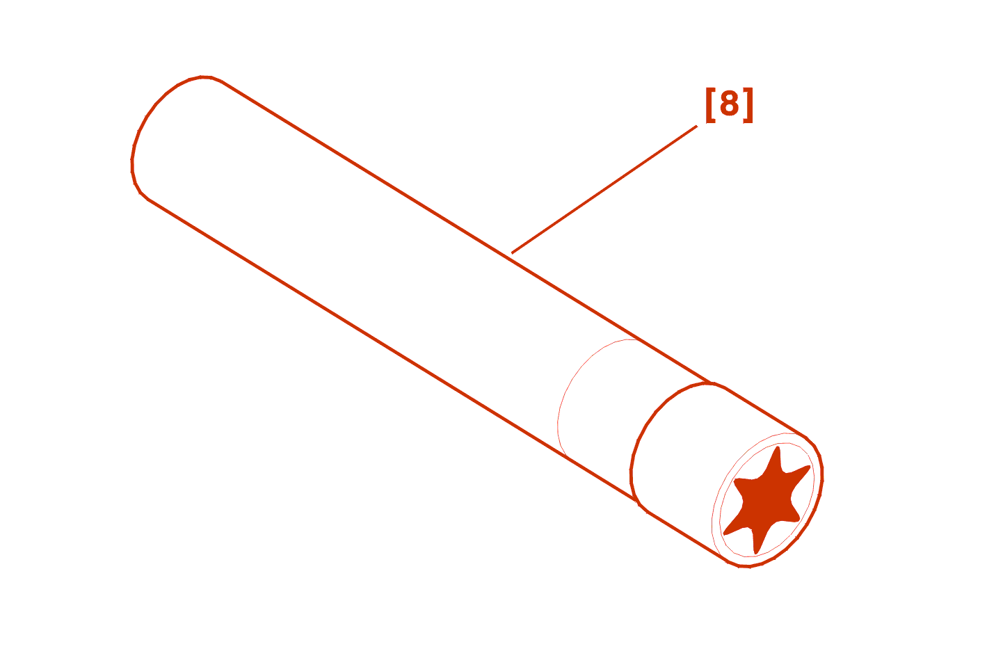
[8] Cylinder head bolt socket (-).0185 .

[9] Pipe spanner (-).1603-G .
[10] Pipe spanner (-).1603-F .
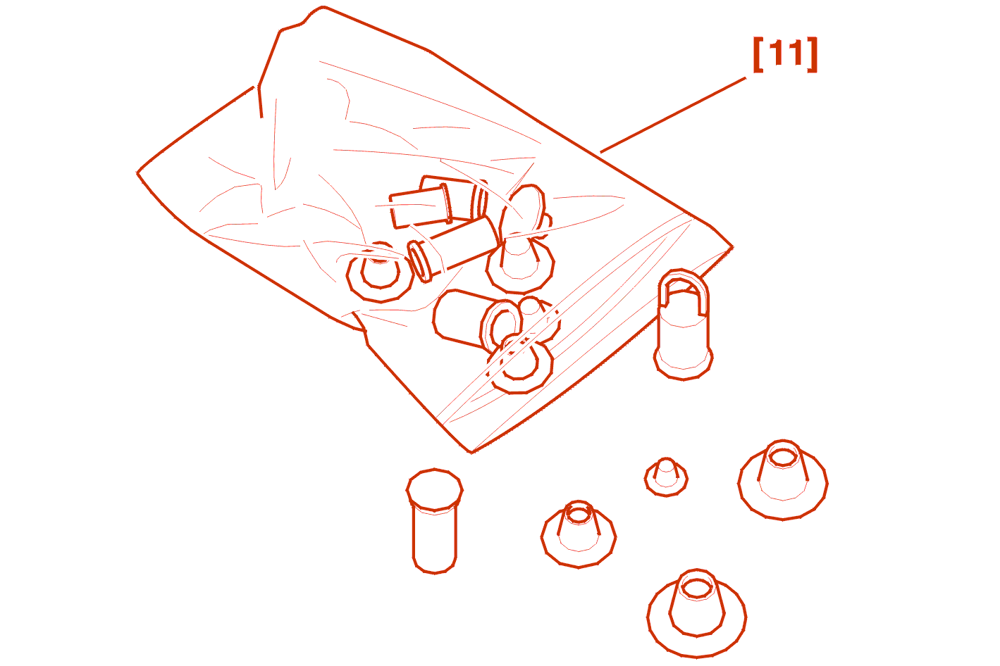
[11] Set of plugs (-).0188-T .

[12] Tightening kit (-).1603-A/B/D/E .
2 - REMOVAL
drain the cooling system .
remove the turbocharger .
remove the timing belt .
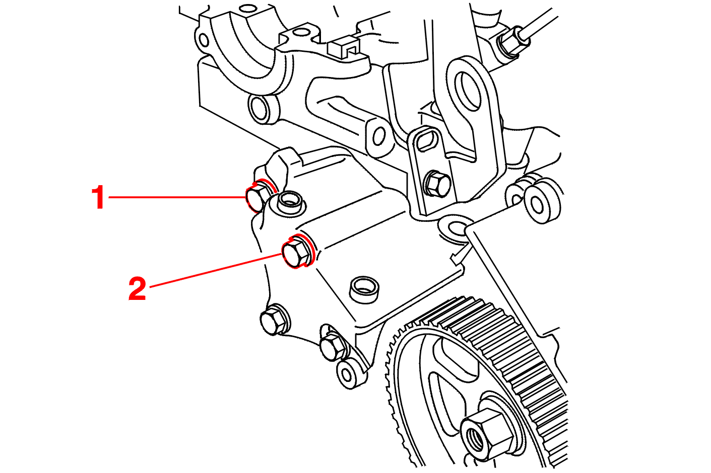
Remove the bolts (1), (2) .
Refit the right-hand engine mounting .
Slightly tighten the bolts .
Place a draining tray under the engine .
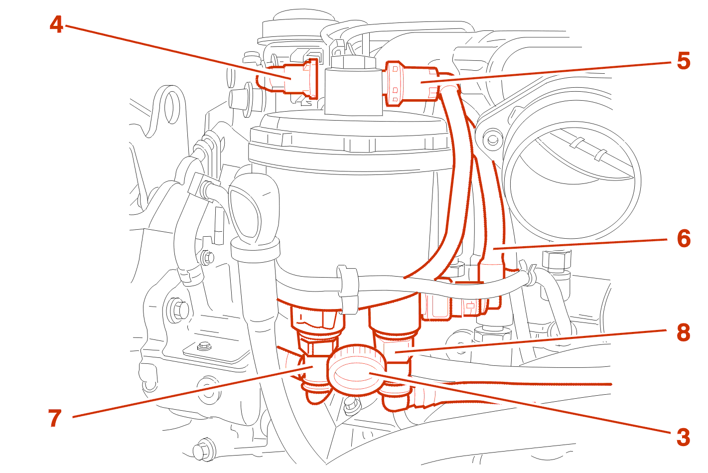
Open the bleed screw (3) .
Move aside the connections (4), (5), (6), (7), (8) .
IMPERATIVE : plug the holes using tool [11] .
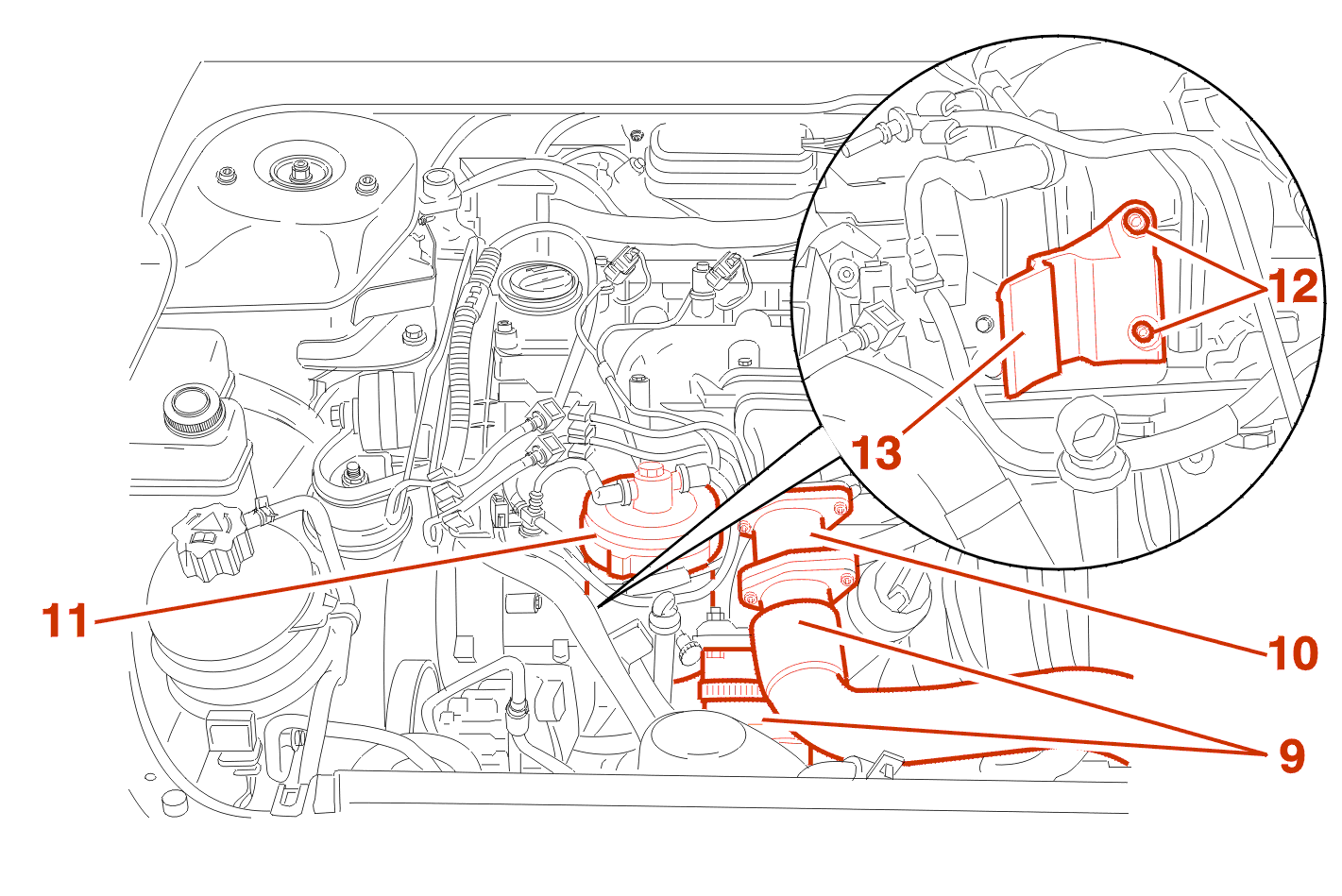
Remove air ducts (9) .
Remove throttle housings and their supports (10) .
Unclip and remove filter element cup (11) .
Remove the bolts (12) .
Remove the filter element reservoir support (13) .

Remove heat exchanger duct (14) from egr valve .
Remove the collar (15) .
Disconnect duct (16) .
Disconnect pipe (17) .
Remove cooling hoses (18) .

Disconnect and separate harnesses from water inlet housing .
Remove the support (19) .
remove injectors .
IMPERATIVE : plug the holes using tool [11] .
remove the camshafts .
IMPERATIVE : clean the fuel unions before slackening .
Disconnect the cylinder head harnesses and pipes and move them aside .
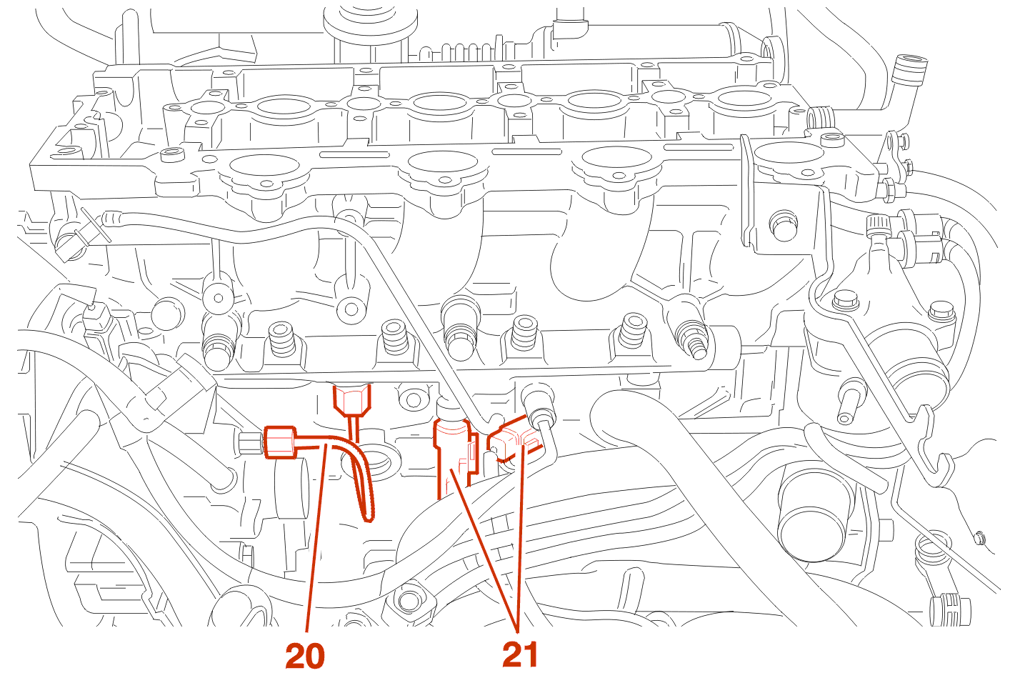
Remove the high pressure pipe (20) .
Plug the holes using tool [11] .
Disconnect connectors (21) from rail .
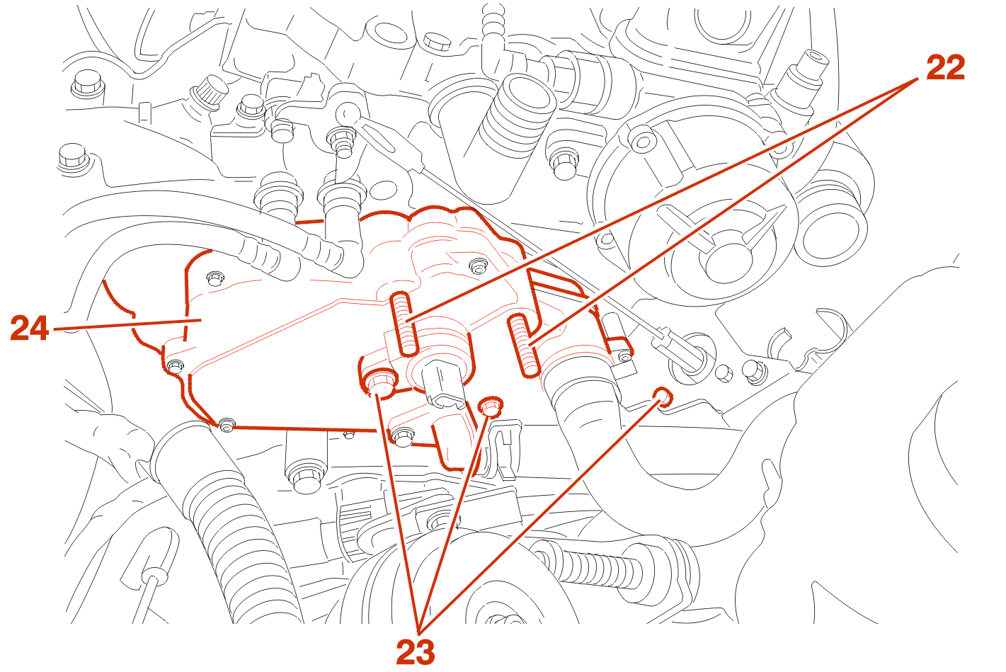
Remove :
Move aside the thermostat housing (24) a little .
IMPERATIVE : starting at the outside and working in a spiral sequence progressively slacken the cylinder head bolts .
Remove the cylinder head bolts (Using the tool [8]) .
Rock and free the cylinder head using levers [5] .
Remove the cylinder head and gasket .
Clean the joint faces with an approved descaling product;Do not use sharp or abrasive tools;The joint faces must not have any trace of knocks or scores .
Clean the threads in the cylinder block with a M12 X 150 tap .
Check the condition :
IMPERATIVE : for checking, rectification or replacement of these parts, refer to the data sections .
3 - CHECKING THE FLATNESS

Maximum permissible bow = 0.05 mm .
4 - CHECKING VALVE PROTRUSION

Clean the checking surfaces .
Check the pocketing of the valves in relation to the cylinder head face (Checking points (A)) .
Calculate the average of the 4 values measured .
(B) Inlet valve = 0.05 mm .
(C) Exhaust valve = 0.05 mm .
These values are obtained by grinding the valve seats .
Lap in the valves (if necessary) .
5 - CHECKING CYLINDER HEAD BOLTS BEFORE RE-USE

(X) must be less than 133.4 mm .
6 - CHOICE OF CYLINDER HEAD GASKET
Remove the crankshaft setting rod [4] .
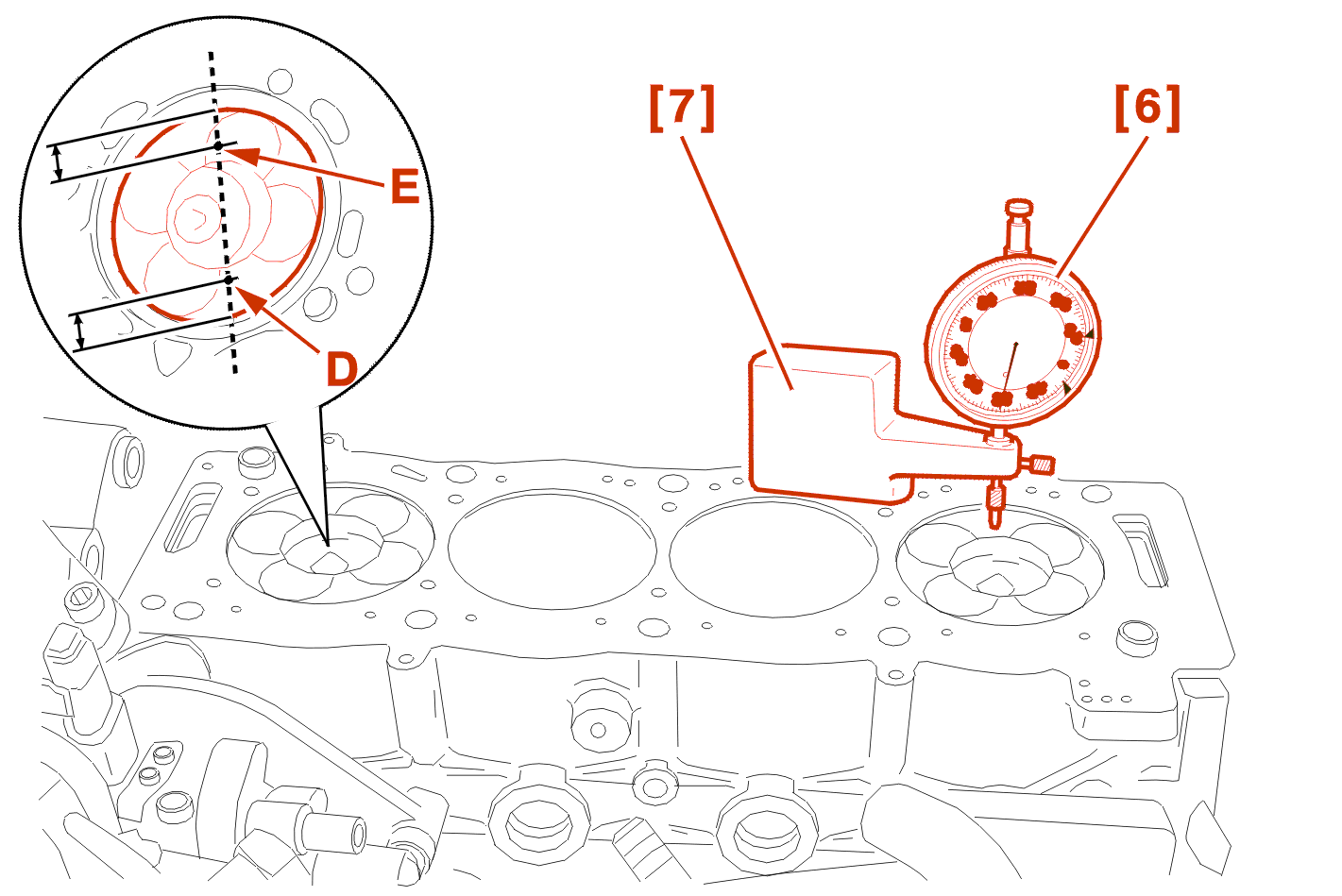
Clean the checking surfaces .
Fit the dial gauge [6] on the bracket [7] .
Turn the crankshaft .
Place the needle of the dial gauge on one of the checking points (Checking point : D) .
Continue turning the crankshaft until the piston reaches TDC .
Read the value .
Turn a quarter turn backwards .
Move the piston to the Top Dead Centre value without ever exceeding it .
Zero the dial gauge .
Move the dial gauge/bracket assembly [6] and [7] over the cylinder block .
Read the value .
Place the needle of the dial gauge on one of the checking points (Checking point : E) .
Zero the dial gauge .
Move the dial gauge/bracket assembly [6] and [7] over the cylinder block .
Read the value .
Calculate the average of the 2 values measured .
Continue in the same way for the other three cylinders .
NOTE : maximum difference between 2 pistons = 0.07 mm .
WARNING : the highest average value determines the thickness of the gasket .
7 - CYLINDER HEAD GASKET IDENTIFICATION

Engine identification marking .
(F) : thickness identification .
There are 4 categories of laminated metal cylinder gaskets .
| piston protrusion measurements | thickness | hole (F) | hole (G) |
|---|---|---|---|
| 0.52 to 0.570 | 1.25 ± 0.04 | 1 | 1 |
| 0.571 to 0.610 | 1.30 ± 0.04 | 1 | 2 |
| 0.611 to 0.650 | 1.35 ± 0.04 | 1 | 3 |
| 0.651 to 0.690 | 1.40 ± 0.04 | 1 | 4 |
IMPERATIVE : if the value measured does not correspond to the values indicated, investigate the origin of the fault (measurement error, handling error etc.) .
8 - REFITTING
Clean the surfaces of the coolant housing outlet .
Turn the crankshaft with the tool [3] .
Peg the flywheel using the rod [4] .
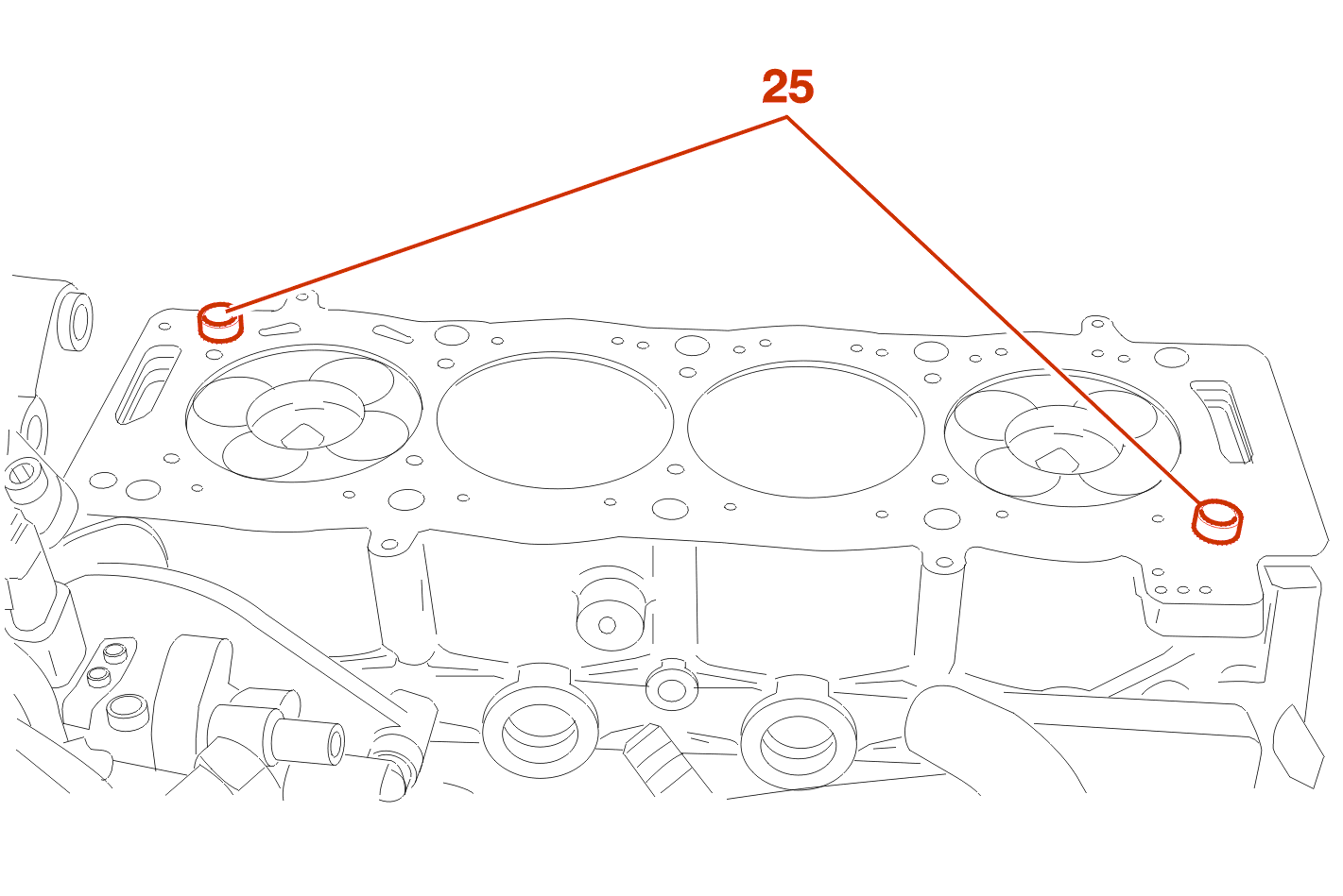
Check that the pins (25) are present .
Fit a new cylinder head gasket (Following the direction of fitting) .
Ensure that the camshaft is pinned .
Refit the cylinder head .
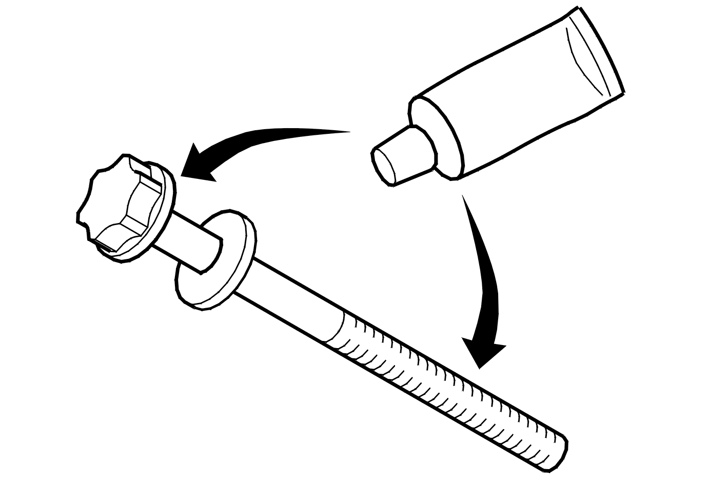
Brush the threads of the cylinder head bolts .
Fit the cylinder head bolts coated with MOLYKOTE G RAPID PLUS on the threads and under the bolt heads .
9 - CYLINDER HEAD TIGHTENING

Tighten the cylinder head bolts in the order shown (Using the tool [8]) .
Stage 1 :
Stage 2 :
Stage 3 :
Stage 4 :
Stage 5 :
Stage 6 :
NOTE : it is not necessary to retighten the cylinder head after bringing the engine up to operating temperature .
10 - REFITTING (CONTINUED)
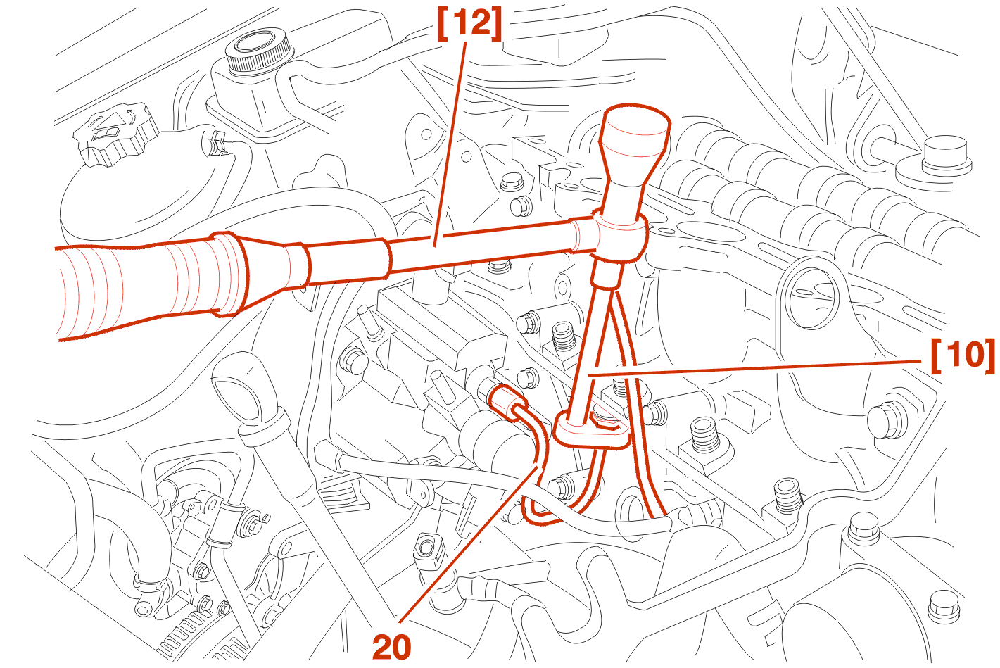
IMPERATIVE : when carrying out an operation on the diesel circuit, respect safety instructions .
WARNING : if any work is carried out on the high pressure pipes they must always be replaced .
Fit :The high pressure supply pipe .
Finger tighten : The hoses .
Tighten the pipe (20) to 2.25 daN.m,Using the tools [10], [12] .
replace camshafts .
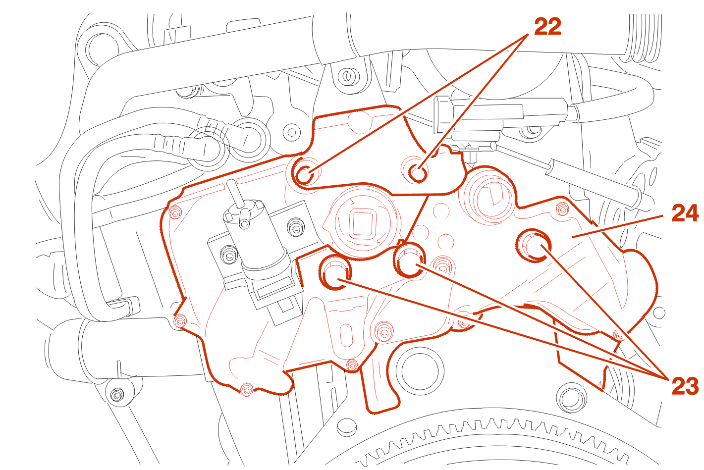
Fit the thermostat (24) with a new joint .
Tighten :
Couple up and clip the harnesses, hoses and cables connected to the cylinder head .
Replace vacuum pump fitted with its new seals .
Tighten pump to 2 dan.m .
Position the cross beam [1] fitted with its chains [2] and take the weight .
Remove the right-hand engine mounting .
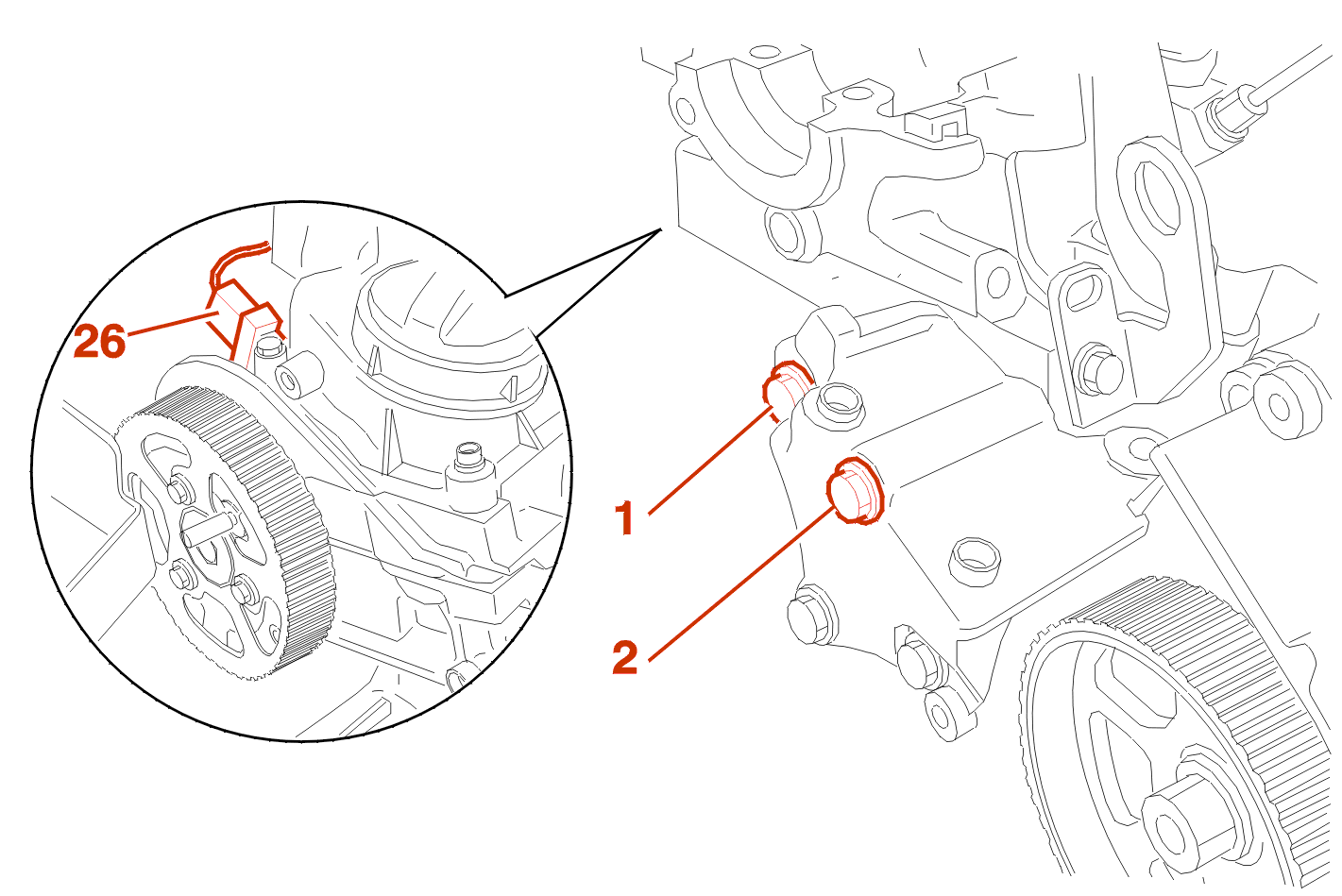
Refit the bolts (1), (2) .
Tighten :
adjust air gap of sensor (26) .
refit the timing belt .
fit the turbocharger .
Continue the fitting operations in the reverse order to removal .
fill and bleed the cooling system .
Carry out the following road test :
Check the sealing of the various unions .