C7AP0ZV1 - 607
FITTING CARAVAN ATTACHMENT
1 - PRESENTATION
1 - 1 - SWAN-NECK BALL TOW HITCH SIARR PART NO. 9527.ER

Tow bar data :
| description | reference | quantity | tightening torque(s) (da.Nm) |
|---|---|---|---|
| central cross member | 1 | 1 | - |
| left-hand linkage arm | 2 | 1 | |
| right-hand linkage arm | 3 | 1 | |
| backplate | 4 | 1 | |
| backplate | 5 | 1 | |
| ball joint | 6 | 1 | |
| bolt (M12 x 100) | 7 | 4 | 8,1 |
| nut (M12) | 8 | 7 | - |
| lock washer (12 x 24) | 9 | 9 | |
| bolt (M12 x 30) | 10 | 2 | 8,1 |
| retainer nut | 11 | 2 | - |
| bolt (M10 x 35) | 12 | 4 | 4,7 |
| plain washer | 13 | 4 | - |
| lock washer (10 x 20) | 14 | 4 | |
| nut (M10) | 15 | 4 | |
| bolt (M12 x 80) | 16 | 2 | 8,1 |
| foam washer | 17 | 5 | - |
| fixing shim | 18 | 2 | |
| tow ball cover | 35 | 1 | |
| bolt (M12 x 90) | 36 | 1 | 8,1 |
| bolt (M6 x 16) | 37 | 1 | - |
| lock washer (6 x 12) | 38 | 1 |
1 - 2 - RDSO TOW BAR (TOW BALL REMOVABLE WITHOUT A TOOL) SIARR PART NO. 9527.ES

Tow bar data :
| description | reference | quantity | tightening torque(s) (da.Nm) |
|---|---|---|---|
| central cross member | 1 | 1 | - |
| left-hand linkage arm | 2 | 1 | |
| right-hand linkage arm | 3 | 1 | |
| backplate | 4 | 1 | |
| backplate | 5 | 1 | |
| ball joint | 6 | 1 | |
| bolt (M12 x 100) | 7 | 4 | 8,1 |
| nut (M12) | 8 | 5 | - |
| lock washer (12 x 24) | 9 | 7 | |
| bolt (M12 x 30) | 10 | 2 | 8,1 |
| retainer nut | 11 | 2 | - |
| bolt (M10 x 35) | 12 | 4 | 4,7 |
| plain washer | 13 | 4 | - |
| lock washer (10 x 20) | 14 | 4 | |
| nut (M10) | 15 | 4 | |
| bolt (M12 x 80) | 16 | 2 | 8,1 |
| foam washer | 17 | 5 | - |
| key | 19 | 2 | |
| mechanism blank | 20 | 1 | |
| tow ball cover | 35 | 1 | |
| bolt (M12 x 90) | 36 | 1 | 8,1 |
| bolt (M6 x 16) | 37 | 1 | - |
| lock washer (6 x 12) | 38 | 1 |
1 - 3 - MONOBLOC BALL TOW HITCH ISO SIARR PART NO. 9527.EQ

Tow bar data :
| description | reference | quantity | tightening torque(s) (da.Nm) |
|---|---|---|---|
| central cross member | 1 | 1 | - |
| left-hand linkage arm | 2 | 1 | |
| right-hand linkage arm | 3 | 1 | |
| backplate | 4 | 1 | |
| backplate | 5 | 1 | |
| ball joint | 6 | 1 | |
| bolt (M12 x 100) | 7 | 4 | 8,1 |
| nut (M12) | 8 | 7 | - |
| lock washer (12 x 24) | 9 | 9 | |
| bolt (M12 x 30) | 10 | 2 | 8,1 |
| retainer nut | 11 | 2 | - |
| bolt (M10 x 35) | 12 | 4 | 4,7 |
| plain washer | 13 | 4 | - |
| lock washer (10 x 20) | 14 | 4 | |
| nut (M10) | 15 | 4 | |
| bolt (M12 x 80) | 16 | 2 | 8,1 |
| foam washer | 17 | 5 | - |
| bolt (M16 x 45) | 21 | 2 | 19,5 |
| lock washer (16 x 32) | 22 | 2 | - |
| nut (HM 16) | 23 | 2 | |
| tow ball mounting | 24 | 1 | |
| tow ball cover | 35 | 1 | |
| bolt (M12 x 90) | 36 | 1 | 8,1 |
| bolt (M6 x 16) | 37 | 1 | - |
| lock washer (6 x 12) | 38 | 1 |
1 - 4 - TOWING CAPACITY
For the towing capacity, consult the vehicle handbook .
2 - FITTING THE TOWBAR
NOTE : the coupling piston will have to be dismantled if it masks the police plate .
2 - 1 - VEHICLE ON A LEVEL SURFACE
Remove the luggage compartment carpet .

Remove the trim .

Remove the trim (On the left-hand side) .
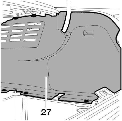
Remove the trim (On the right-hand side) .
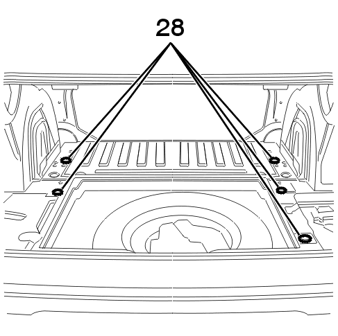
Remove : The blanks .
Keep the closers in order to re-seal the body when dismantling the coupling .

Centre and stick the foam washers onto the and backplates .

Engage :
2 - 2 - WITH THE VEHICLE ON A LIFT

Remove :

Remover the brackets from the abr sensor wiring harness .

Carefully trim the bumpers according to the dimensions .

Engage the retainer nut in the exhaust side of the rear panel .

Engage the retainer nut in the right side back panel .
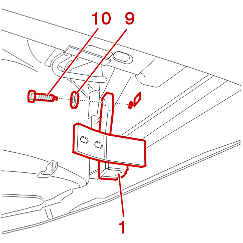
Join the central cross member to the back panel on the exhaust side without blocking the and fixings .

Join the central cross member to the right side back panel without blocking the and fixings .
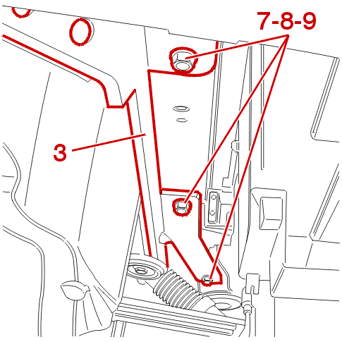
On the right-hand side :

Exhaust side :
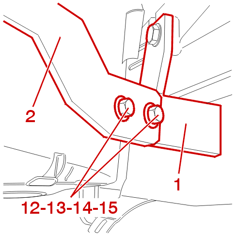
Exhaust side :
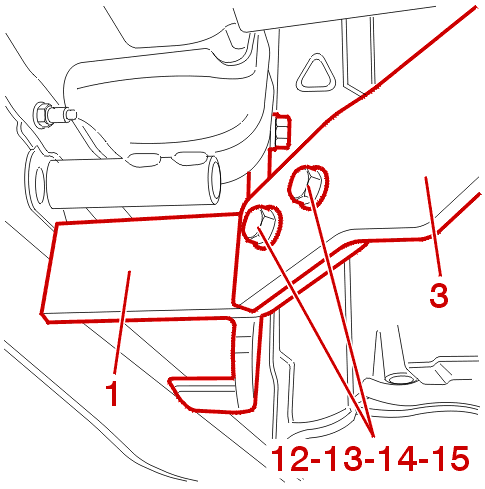
On the right-hand side :
Order of tightening of towbar components :
NOTE : for this procedure, 2 operators are required: one in the boot and one under the vehicle .
2 - 3 - REASSEMBLY
Refit the parts in the reverse order of removal .

Fix the heat-shield plate with the fixings .
3 - SWAN NECK TOW BALL

Fix the ball, the shims to the cross member with the fixings .
Tighten the mountings to the specified torque .
IMPERATIVE : the tightness of the bolts must be checked after the first kilometres of towing .
4 - MONOBLOC TOW BALL

Secure the tow ball mounting to the towbar crossmember using the fasteners and .
Secure the tow ball to the tow ball mounting using the fasteners and .
Tighten the mountings to the specified torque .
IMPERATIVE : the tightness of the bolts must be checked after the first kilometres of towing .
5 - TOW BALL REMOVABLE WITHOUT A TOOL
5 - 1 - BALL POSITION
Remove the closers from the coupling housing .
Engage and clip the ball in the coupling housing .

Ensure that the green mark of the roller faces the green mark of the ball .
Lock the ball by turning the key to the left .
Remove the key .
5 - 2 - BALL REMOVAL

Engage the key then unlock the ball by turning the (19) key to the right .
Hold the ball in place .
Pull the (34) roller towards you .
Turn the (34) roller to the right .
Remove the key .
The (C) red mark of the roller is to be found opposite the (B) green ball mark .
NOTE : regularly grease the ball mechanism with a resin-free grease or oil .