C7AP12K1 - 607
FITTING CD PLAYER
IMPERATIVE : this device must be installed by a professional .
1 - PRESENTATION

(1) CD player .
(2) Control on the steering column .
(3) Radio .
(4) Multi-function display .
(5) Speaker .
2 - COMPOSITION OF THE CD CHANGER (PART NO. 6564.45)

| reference | description | quantity |
|---|---|---|
| 1 | CD player | 1 |
| 6 | cd cartridge | 1 |
| 7 | cartridge operating instructions | 1 |
WARNING : additional parts to be ordered, depending on the equipment level and the trim colour .
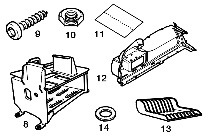
| reference | description | Part No. | quantity | fitting |
|---|---|---|---|---|
| 8 | cd changer support | 6560.K2 | 1 | without satellite navigation system |
| 9 | cd changer mounting bolt | 6920.21 | 1 | all models |
| 10 | nuts | 6935.A6 | 3 | without satellite navigation system |
| 11 | template for cutting out | supplied with the assembly manual | 1 | with on-board navigation system |
| 12 | luggage compartment trim | 7465.YK | 1 | without satellite navigation system |
| 13 | cd support | 7465.YN | 1 | all models |
| 14 | fixing clips | see Parts microfiche | 4 | all models |
3 - SCHEMATIC DIAGRAM
CD player .

| list of components | |
|---|---|
| 7215 | multifunction screen |
| 8408 | audio amplifier |
| 8409 | heated rear screen aerial assembly |
| 8410 | radio |
| 8413 | radio control |
| 8415 | CD player (1) |
| 8420 / 8425 / 8430 / 8435 / 8440 / 8445 / 8450 / 8452 / 8455 / 8457 |
speakers |
| BSI | built-in systems interface (BSI) |
4 - VEHICLE PREPARATION
Open the bonnet .
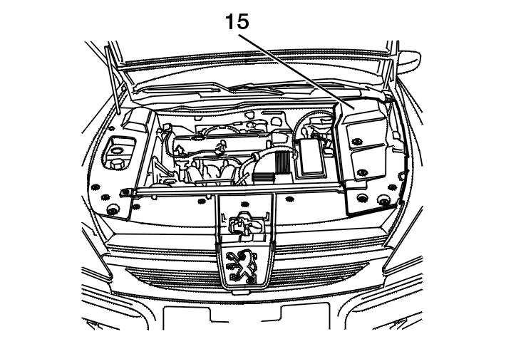
Remove the style cover (15) .
Disconnect the battery + terminal .

Special feature - Dual battery :
A battery must be disconnected :
IMPERATIVE : DISCONNECT THE STARTING BATTERY ; remove the auxiliary battery (16) supply fuse to cut off the electrical supply .
5 - FITTING : CD PLAYER
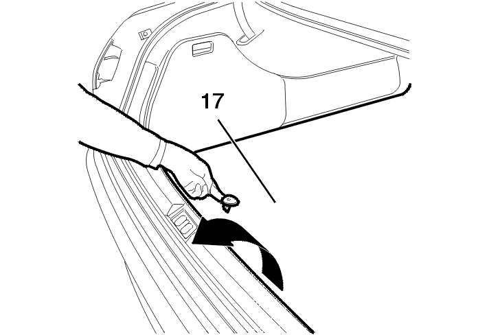
Remove the luggage compartment carpet (17) .

Unclip the side fixings (18) of the boot sill trim (19) .
Pass the tool [20] - (-).1339 into the hole located at (21), then pull towards the inside to unclip the trim at the bottom (3 clips) .
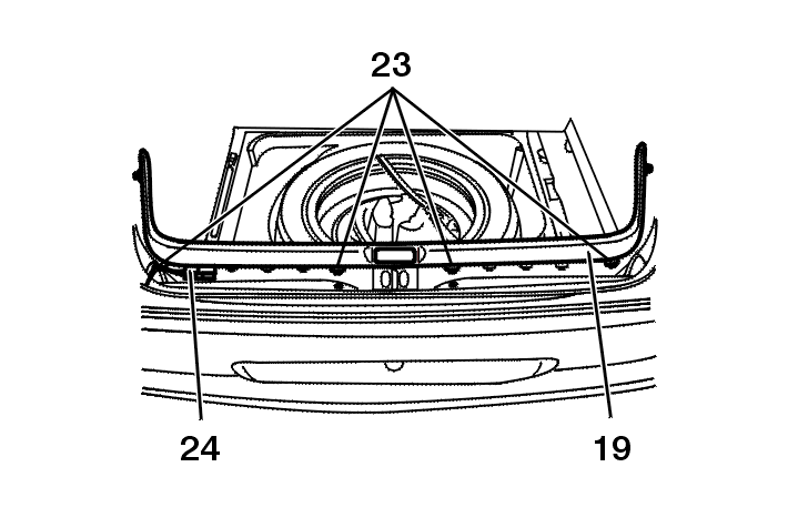
Then pull the trim upwards to detach the clips (19) .
Disconnect the luggage compartment light connector (24) .
Remove the boot sill trim (19) .
5 - 1 - WITH ON-BOARD NAVIGATION SYSTEM

Unclip :
Move aside the boot side trim (27) then release it from the swan neck mounting (28) and the boot seal (29) .

Position the cut-out gauge (11) on the trim (27) .
Mark the contour .
Cut out the trim following the line (30) .
5 - 2 - WITHOUT SATELLITE NAVIGATION SYSTEM

Unclip :

Unclip :
Detach the side trim (35) .
Remove the luggage compartment side trim (35) .

Replace the original boot side trim (35) with trim (12) : Part No. 7465.YK .
Cut out the trim at the top following the pre-marking (36) .

Fit the support (8) using 3 nuts (10) : Part No. 6935.A6 .
5 - 3 - ALL MODELS

Unclip the MQS 16-way blue connector provided on the main harness (37) .
Connect the 16-way blue connector (37) to the cd changer (1) .
Slide the cd changer in the support (1) at the bottom (8) .

Secure the cd changer (1) in the support using a bolt (9), part number 6920.21 .
6 - FITTING : CD SUPPORT
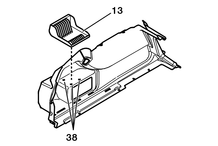
Position the cd support (13) on the trim .
Mark the securing holes (38) .
Drill a hole in the trim following the marking .
Secure the cd support using clips (14) .
7 - INITIALISATION : TOOL DIAG 2000
IMPERATIVE : the vehicle must be configured following fitting in order for the cd changer .

Connect the tester DIAG 2000 .

A = Consultation and diagnosis per vehicle .
B = Information DIAG 2000 .
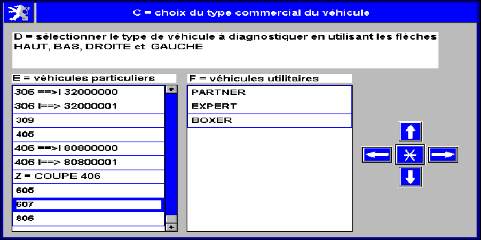
C = Choice of vehicle type .
D = Select the type of vehicle to be diagnosed using the up, down, right and left arrows .
E = Cars .
F = Vans .
Z = 406 coupe .

A = Consultation and diagnosis per vehicle .
G = Vehicle identification :

G = Vehicle identification .
H = Enter the number for accurate identification of the vehicle .

A = Consultation and diagnosis per vehicle .
I = Diagnosis .
J = Downloading .
K = Replacement parts .
L = Dealer fit .
M = Activation and disarming of the functions .

L = Dealer fit .
N = When fitting an accessory, it is necessary to reconfigure the vehicle .
O = This menu enables you to automatically configure all the ECUs necessary .
P = These accessories are :

L = Dealer fit .
Q = You wish to fit as an accessory .
P1 = Alarm .
P2 = On-board navigation system .
P3 = CD player .
P4 = Dual battery unit / Battery .
P5 = Tyres .
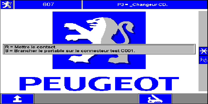
P3 = CD player .
R = Switch on the ignition .
S = Connect the portable to the test connector C001 .

P3 = CD player .
T = System identification - Reading of the ECU in progress .

P3 = CD player .
U = Configuration : CD player .

V = Cd changer configuration .
W = Configuration carried out .
X = Validate to continue .
8 - REFITTING THE COMPONENTS
Proceed in the reverse order to removal .
Special feature - Dual battery :
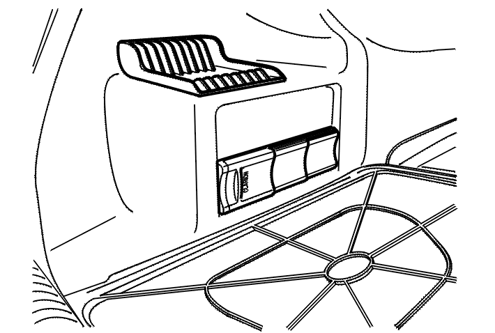
9 - HANDBOOK
See vehicle handbook .
NOTE : notice valid subject to product modification .