E5AQ01F1 - 607
SETTING UP ENGINE SUB-FRAME CHECKING EQUIPMENT
1 - SPECIAL TOOLS
1 - 1 - CHECKING GAUGE FOR FRONT MOUNTINGS OF THE FRONT WISHBONE ON THE SUB-FRAME (-).1107
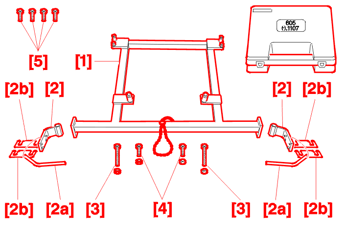
Including :
The purpose of this tooling is to determine accurately, without dismantling, whether the sub-frame needs to be replaced .
It is possible to use it to check the angles of slope of the yokes (caster 1°, camber 5°) for mounting the front wishbones on the sub-frame, first one side then the other, (or both sides at the same time) which are liable to be twisted following an impact .
1 - 2 - TOOLS FOR CHECKING THE SUB-FRAME AFTER FRONT IMPACT (ADDITION TO TOOLING (-).1107)

The complete sub-frame checking kit (-).1107-ZZ, Including :
The purpose of this tooling is to determine, without dismantling, whether it is advisable to replace the sub-frame after a front impact .
It enables a check to be made as to whether there is twisting of the sub-frame at the end of the chassis leg after an impact .
2 - CHECKING OF FRONT WISHBONE MOUNTINGS ON ENGINE SUB-FRAME
WARNING : this gauge is to be used after a front suspension check .
2 - 1 - REPAIR ON VEHICLE

Remove :
2 - 2 - CHECK
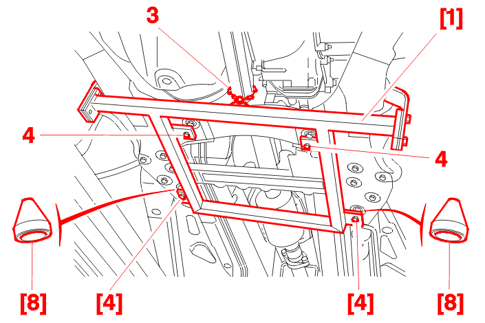
Position the 2 centralising pins [8] on the frame [1] .
Hook the gauge on using the small chain (3) :
Pivot and position the gauge, ensuring that the centralising pins are inside the perforations of the sub-frame, and fit the sub-frame with the [4] bolts and the 2 nuts for fitting the steering rack housing (4), tightening them a moderate amount (The bolts [4] are supplied in the kit) .

Position the checking yoke [2], pin with bolts [5], fasten with bolts 1 mm [2b], insert a shim [5] (nominal setting), tighten the bolts [2a] and pin them with the drift .
If pinning is impossible :
After making these three checks, if pinning proves impossible: replace the sub-frame .
2 - 3 - OPERATION ON SUB-FRAME WHICH HAS BEEN REMOVED
These checks can also be carried out by offering up the sub-frame on its own, on the gauge which has previously been laid flat .
3 - SUB-FRAME CHECK AFTER FRONT IMPACT
3 - 1 - OPERATION ON GAUGE
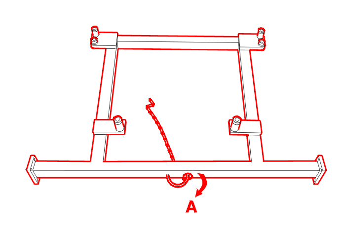
Bend the ring 90 to (A) °, in order to avoid any contact with the sub-frame .
3 - 2 - REPAIR ON VEHICLE
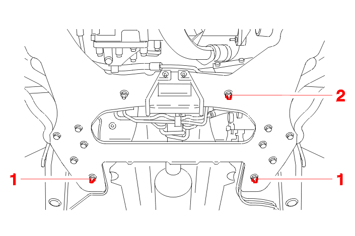
Remove :
3 - 3 - CHECK
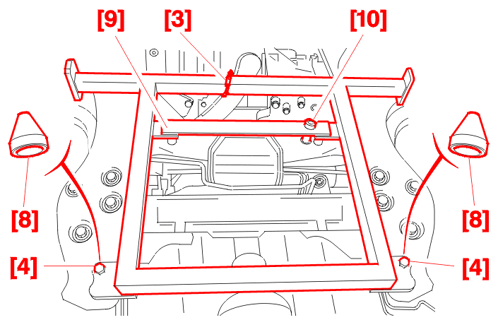
Position the 2 centralising pins [8] on the frame [1] .
Hook the gauge on using the small chain (3) .
Pivot and position the gauge, ensuring that the centralising pins are inside the perforations of the sub-frame and mount the sub-frame using bolts [4], tightening them a moderate amount (The bolts [4] are supplied in the kit (-).1107) .
Position the mounting plate [9] on the gauge and secure it using the mounting ring [10] supplied .
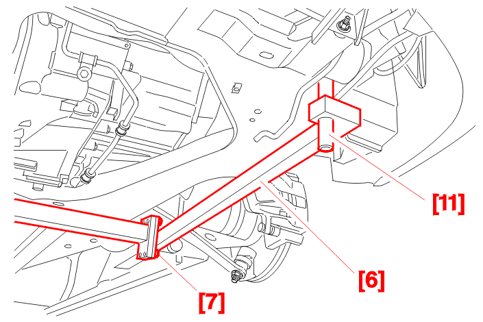
Position the extension [6] on the gauge and secure it using the 2 bolts [7] supplied, on the side to be checked .
Using the checking pin[11], place it in the sub-frame mounting hole, supported by the sub-frame .
Check the conformity of .
NOTE : the check only takes place with the sub-frame in place and fitted at 3 points (never remove the 2 sub-frame front mounting bolts at the same time) .
3 - 4 - CHECKING THE CORRECTNESS OF THE SUB-FRAME

[6] : Extension .
[11] : Checking pin .
(5) : Sub-frame .
(A), (B) : Negative check, Part outside tolerance, sub-frame to be replaced following impact .
(X) : Reference interval .
(Y) : Reference surface .
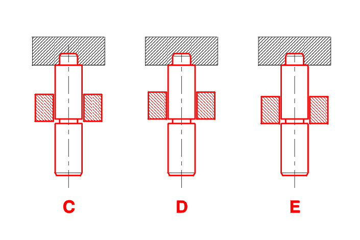
(C), (D), (E) : Check correct, Part within the tolerances, sub-frame not twisted .
4 - TIGHTENING TORQUE(S)
Rear bolts mounting the sub-frame on the body : 6.5 da.Nm .
Mounting nut for the steering rack housing : 8 da.Nm .
Front bolts mounting the sub-frame on the body : 10 da.Nm .
5 - COMMENT(S)
After use, store in the small case (-).1107 already in your possession :