B2CJ0VK1 - 607 ML5T GEARBOX
ASSEMBLY GEARBOX CONTROL PLATE
1 - PRELIMINARY OPERATIONS
Removal :
Dismantling : GEARBOX CONTROL PLATE .
2 - ASSEMBLY

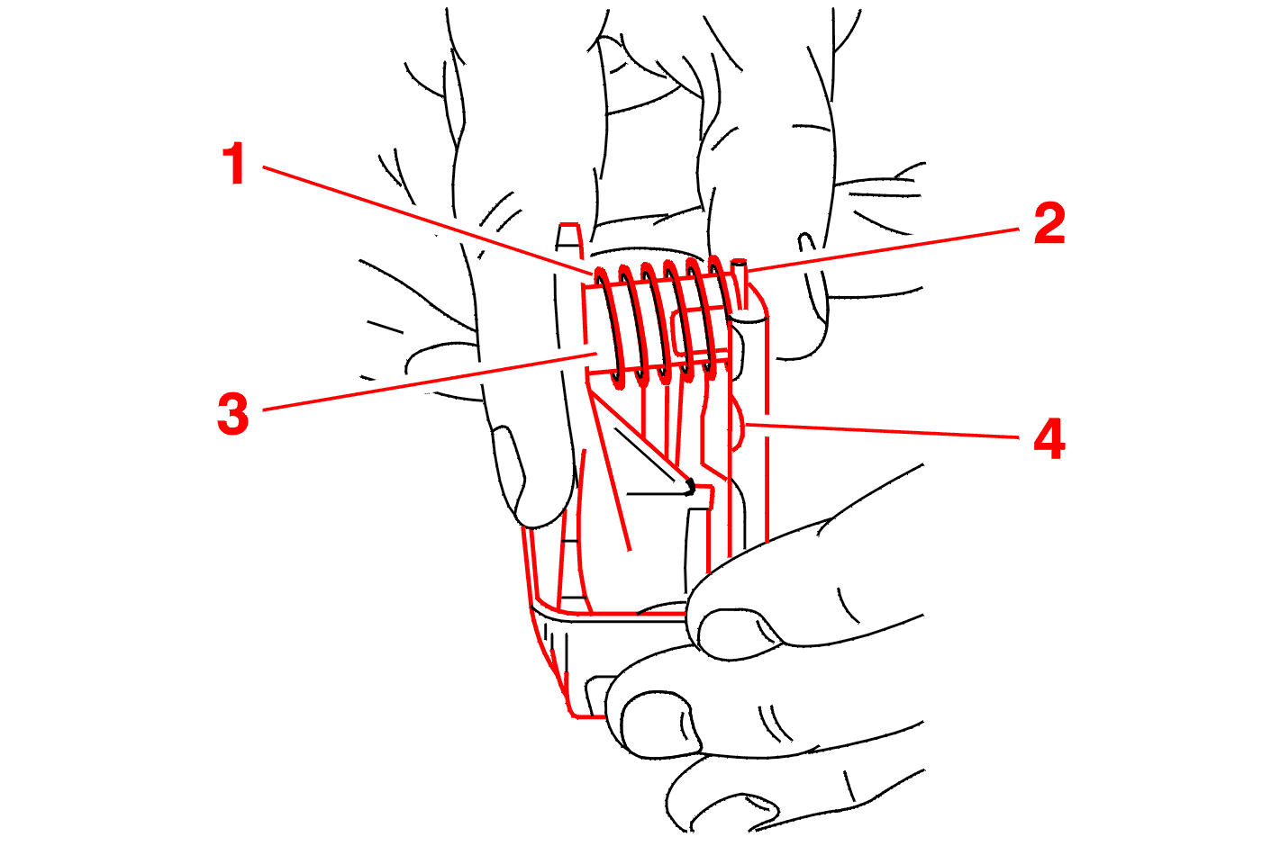
Position the spring (1) on its guide (3) and compress it with the roller (2), then position it in the notch (4) .

Compress the spring (5) .
Position the fork (6) between the spring (5) and the washer (7) .

Fit :

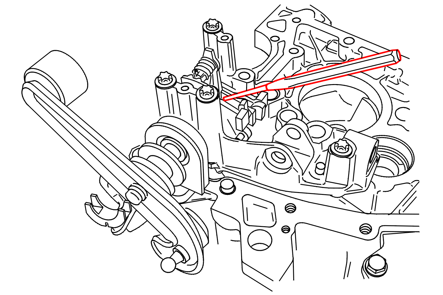
Fit new tension pins .

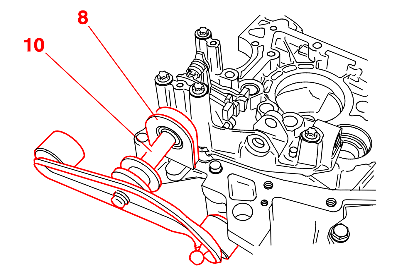
Position the 1 st/2 nd shaft (10) in its needle roller bearing .
Select in the direction of arrow (E) .
Engage the gear in direction (F) .

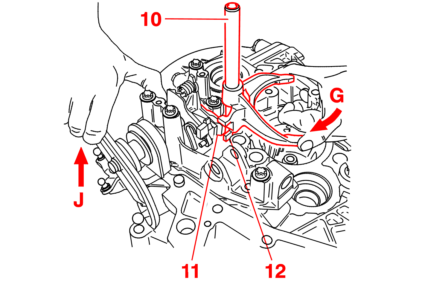
Rotate the 1 nd/2 rd shaft (10) in the direction of arrow (G) to position the dog (11) in the housing (12) .
Return the plate to neutral by moving in the direction of arrow (J) .

Insert the 3 rd/ 4 th shaft (14) in its bore (15) .
Engage the gear in direction (I) .
Select in the direction of arrow (J) .
Rotate the 3 nd/4 rd shaft (14) in the direction of arrow (K) to position the dog (11) in the housing (13) .

Return the plate to neutral by moving in the direction of arrow (L) .
The roller (16) is in the middle notch .

Select in the direction of arrow (M) .
Engage the gear in direction (N) .
Insert the 5 th speed shaft (17) in its bore (18) .
Disengage the gear verifying that the dog (19) is positioned in the notch (20) .

Move the control to the neutral position .
Remove the bolts (21) .
Fit the stop plate .