B3BF09K1 - 607
SUSPENSION SETTING
WARNING : to check all the angles (castor, camber, tracking), it is necessary to place the vehicle at reference height .
IMPERATIVE : for a complete check of the alignment of the front and rear axles, start with the rear axle .
1 - SPECIAL TOOLS
Suspension height setting equipment (-).0916 .

[1] set of two suspension compressors (-).0916-A .
[2] set of four shackles (-).0916-C .
[3] set of four setting rods (-).0916-D .
[4] set of four straps (-).0916-B .

[5] sub-frame centring pin (-).0623-C .
[6] Set of positioning calipers (-).0532-B .
2 - RECOMMENDATION BEFORE SETTING THE VEHICLE TO THE REFERENCE HEIGHT
Check the conformity and the inflation pressures of the tyres .
2 - 1 - FRONT SUSPENSION

Check the position of the sub-frame, in relation to the body, using the tools [5] .
2 - 2 - REAR SUSPENSION

Check the position of the rear crossmember in relation to the body using the tools [6] .
2 - 3 - RACK MID-POINT
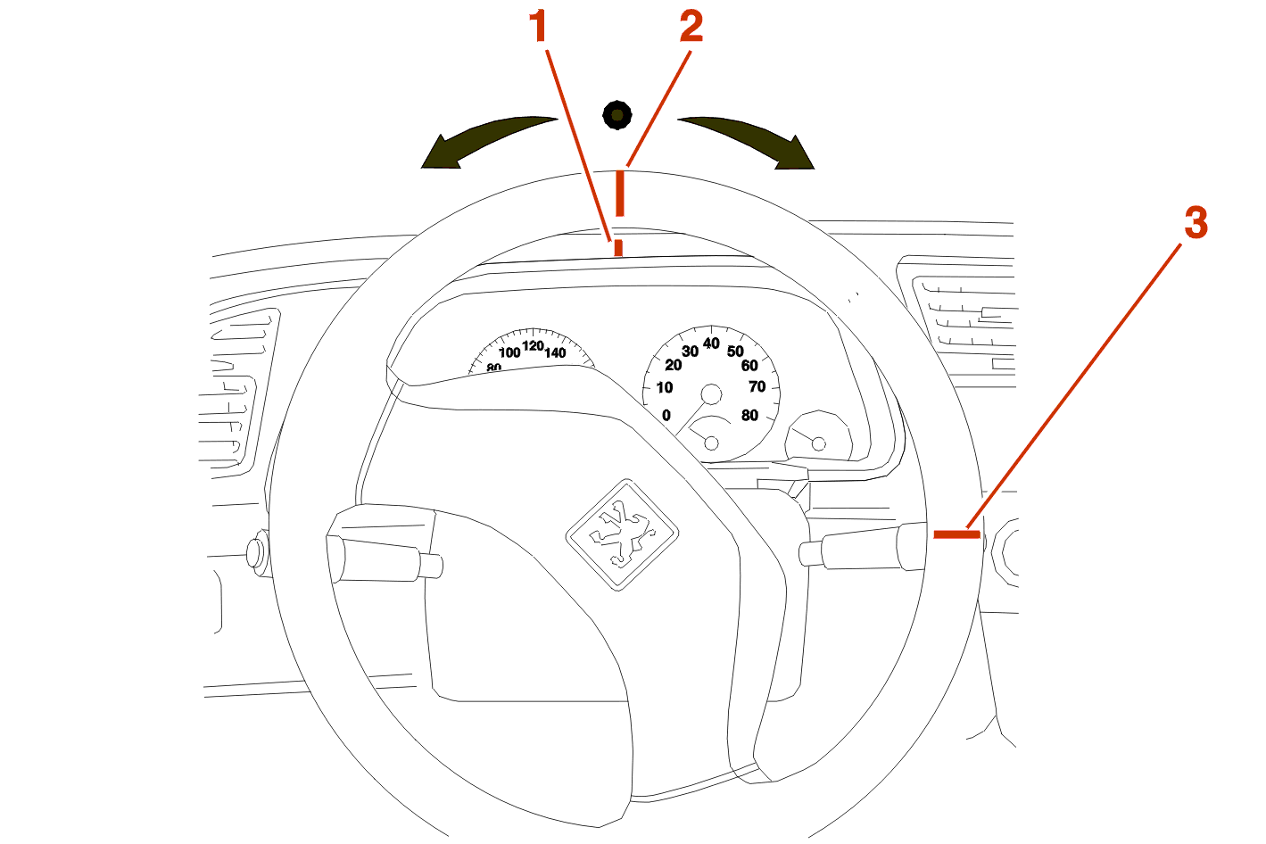
Turn the steering wheel to maximum lock on one side .
Make a mark (1) on the fascia and a mark (2) on the steering wheel opposite the first mark .
Turn the steering wheel to maximum lock on the other side counting the number of turns of the wheel .
Make a second mark (3) on the wheel opposite the mark on the fascia .
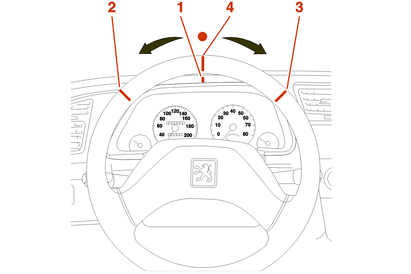
Halve the distance between the 2 steering wheel marks and make a 3rd mark (4) .
Return the steering wheel halving the number of turns .
Line up the 3rd mark (4) with the fascia mark (1) .
IF REQUIRED, REALIGN THE STEERING WHEEL WITH THE FASCIA, BY REMOVING AND REFITTING THE WHEEL .
2 - 4 - RECOMMENDATIONS
Correct any out-of-true of the wheels .
The front and rear axle alignment value checks and the adjustment of the front and rear axles must be carried out using precise suspension compression positions (setting height) on an axle checking rig .

IMPERATIVE : the front axle on vehicles fitted with an esp system must be perfectly aligned in relation to the rear axle (line of symmetry or centreline of the body), the tolerance is ± 1° .
IMPERATIVE : it is compulsory to reinitialise the steering wheel sensor if the front or rear tracking is altered .
3 - SETTING THE REFERENCE HEIGHT
3 - 1 - AT THE FRONT
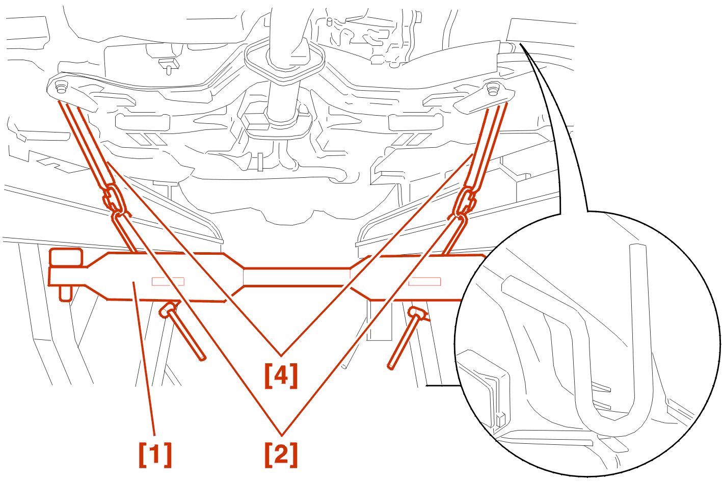
Engage the tie straps [4] fitted with their shackles [2] in the lashing rings .
Fit the suspension compressor [1] .
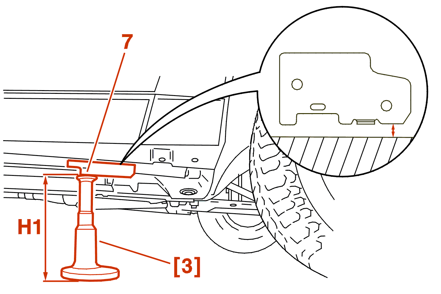
Compress the suspension to obtain a body height H1 (reference height) both sides, measured between the flange (7) and the ground .
WARNING : take the height of the turntables into account when measuring the reference height H1 .
3 - 2 - AT THE REAR
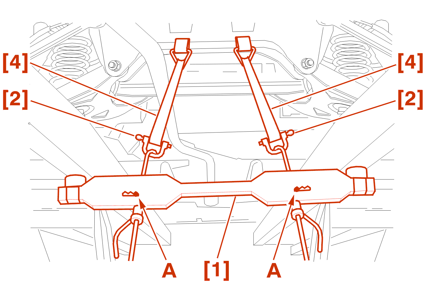
Position the two straps [4] fitted with their shackles [2] over the rear cross member .
Fit the suspension compressor [1] .
Select the most suitable notches (A) to pull on the straps as nearly vertically as possible .

Compress the suspension to obtain a body height H2 (reference height) both sides, measured between the flange (8) and the ground .
WARNING : take the height of the turntables into account when measuring the reference height H2 .
Check that the height H1 measured at the front has not changed (The same applies for H3 and H2 + 50 mm) .
4 - CHECK AND ADJUSTMENT OF THE FRONT AXLE
4 - 1 - CHECK
| characteristics of the front axle | ||
|---|---|---|
| engine code | ||
| description | 3FZ - 4HX 4HZ - XFX |
3FZ - 4HX 4HZ - XFX |
| special features | 225/55R16 | 225/50R17 |
| H1 (mm) | 134 | 140 |
| tracking by wheel (mm) | + 0.5 ± 0,5 | + 0.5 ± 0,5 |
| tracking by wheel (°) | + 0° 04' ± 3' | + 0° 04' ± 3' |
| camber | -0° 15' ± 20' | -0° 15' ± 20' |
| castor | + 2° 30' ± 30' | + 2° 30' ± 30' |
| pivot angle | + 13° 45' ± 30' | + 13° 45' ± 30' |
4 - 2 - TRACK ADJUSTMENT
Only the track is adjustable (At the front) .
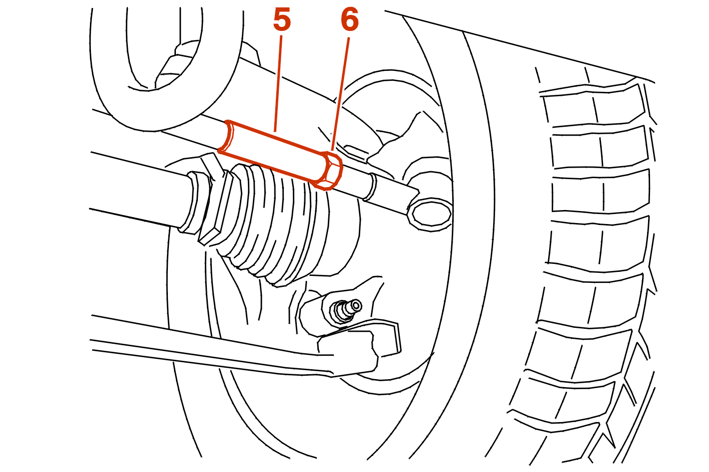
If the value is incorrect, adjust the track rods (5) (one turn of the rod = 2 mm approximately) .
Tighten the nuts (6) to 6 da.Nm .
IMPERATIVE : for a vehicle fitted with the esp system, programme the steering wheel angle sensor using the diagnostic equipment DIAG 2000 .
5 - CHECK OF THE REAR AXLE
Only the variation in the tracking can be adjusted at the rear .
WARNING : any adjustment of the rear axle automatically involves adjustment of the front axle .
| rear suspension data | ||
|---|---|---|
| engine code | ||
| description | 3FZ - 4HX 4HZ - XFX |
3FZ - 4HX 4HZ - XFX |
| special features | 225/55R16 | 225/50R17 |
| H2 (mm) H 3 (mm) |
136 86 |
142 92 |
| camber | -1 ° 18' ± 30' | -1° 18' ± 30' |
| tracking by wheel for H2 (mm) |
+ 2,2 ± 0.5 | + 2,2 ± 0,5 |
| tracking by wheel for H2 (°) |
0° 18' ± 4' | 0° 17' ± 4' |
| tracking by wheel for H3 (mm) |
+ 3,5 ± 0,5 | + 3,5 ± 0,5 |
| tracking by wheel for H3 (°) |
0° 29' ± 4' | 0° 27' ± 4' |
| tracking by wheel for H2 + 50 (mm) |
+ 1,5 ± 0,5 | + 1,5 ± 0,5 |
| tracking by wheel for H2 + 50 (°) |
0° 13' ± 4' | 0° 12' ± 4' |
5 - 1 - CHECK OF THE TOE-IN WHEEL BY WHEEL
Compress the suspension to obtain the body height H2 on each side of the vehicle .
Compare the values recorded on the checking equipment, on the right and on the left, with the toe-in value wheel by wheel corresponding to the body height H2 .
Note the values recorded on the right and on the left .
5 - 2 - CHECK THE TOE-IN VARIATION WHEEL BY WHEEL
Compress the suspension to obtain the body height H3 on each side of the vehicle .
Compare the values recorded on the checking equipment, on the right and on the left, with the toe-in value wheel by wheel corresponding to the body height H3 .
Note the values recorded on the right and on the left .
Release the suspension to obtain the body height H2 + 50 mmon each side of the vehicle .
Compare the values recorded on the checking equipment, on the right and on the left, with the toe-in value wheel by wheel corresponding to the body height H2 + 50 mm .
Note the values recorded on the right and on the left .
6 - ADJUSTMENT OF THE REAR AXLE


6 - 1 - PRE-ADJUSTMENT OF THE CAMS AND LEVERS
NOTE : to make the adjustments easier, lubricate the cams (10) and the levers (9) .
Cams :
Levers :
6 - 2 - ADJUSTMENT OF THE TOE-IN WHEEL BY WHEEL
Compress the suspension to obtain the body height H2 on each side of the vehicle .
Operate the levers (9) to obtain exactly the toe-in value wheel by wheel corresponding to the body height H2 .
Tighten the cam rings (10) to 5.5 daNm lbf. ft.) .
Note the adjusted values (X) on the right and on the left .
Release the suspension to spread the stresses in the flexible mountings .
6 - 3 - ADJUSTMENT OF THE TOE-IN VARIATION WHEEL BY WHEEL
Operate the cams (10) to obtain the exact toe-in value wheel by wheel corresponding to the body height H2 .
Tighten the cam rings (10) to 5.5 daNm lbf. ft.) .
Note the adjusted values (X) on the right and on the left .
Compress the suspension to obtain the body height H3 on each side of the vehicle .
Operate the levers (9) to obtain exactly the toe-in value wheel by wheel corresponding to the body height H3 .
Tighten the levers (9) to 3.5 dan.m .
Release the suspension to obtain the body height H2 + 50 mmon each side of the vehicle .
Operate the levers to obtain exactly the toe-in value wheel by wheel corresponding to the body height H2 + 50 mm .
Tighten the levers to 3.5 dan.m .
Check the toe-in value wheel by wheel corresponding to the body heights H3 and H2 + 50 mm .