B3EG0SK1 - 607
REMOVAL-REFITTING OF THE STEERING MECHANISM
1 - SPECIAL TOOLS

[1] ball joint extractor (-).0709 .
2 - REMOVAL
NOTE : use a wheel free lift .
Position the steering wheel in a straight line .

Remove : The trim (1) under the fascia .

Press button (2) to laterally lock the steering column .
Remove the bolt (3) .
Release the steering universal joint by moving aside the safety clip (A) .
Remove the securing bolts (4) .
Move aside the accelerator pedal and its bracket .
Remove the bolts (5) .
Remove the seal (6) .

Remove the bolts (7) .
Remove the steering column shaft, including the lower universal joint (8) .
Lift and support the vehicle with front wheels suspended .
Remove :
Using the extractor [1] detach the ball joints .
WARNING : to prevent the power steering circuit becoming contaminated, close the two openings of the distributor valve and the two steering pipes using plastic blanks .
Remove : The exhaust pipe .

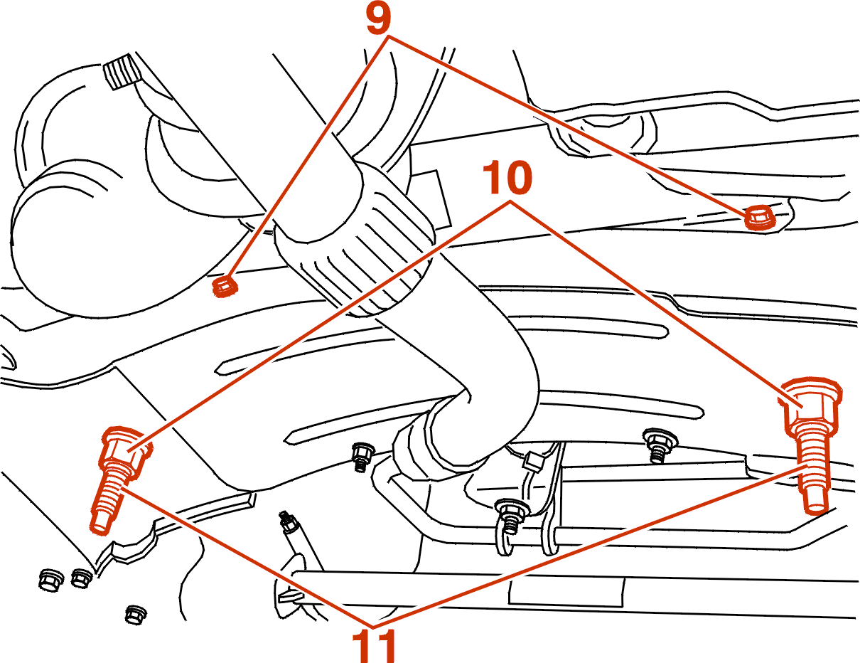
Remove the 2 fixing bolts (9) on the heat shield .
Remove the nuts (10) .
Remove the studs (11) using a TORX 20 type tool .

Remove the steering rack heat shield (12) .
NOTE : retrieve the notched washers between the mechanism and the sub-frame .
VARIABLE POWER STEERING

Disconnect and unclamp the converter wire (13) .

ALL MODELS
Remove :
3 - REFITTING
Always renew :
Fit : The steering mechanism .
WARNING : do not forget to refit the toothed washers between the steering rack and the sub-frame .
IMPERATIVE : tighten the pins (11) to 1 daN.m: a tightening torque greater than 1 daN.m will damage the steering mechanism .
Continue the fitting operations in the reverse order to removal .
VARIABLE POWER STEERING
Re-connect and re-clamp the converter wire (13) .
ALL MODELS
Set the wheels straight ahead .
Position the steering wheel straight ahead .
Refit the steering column pin (8) .
Refit the bolt (3) .
Pull the knob (2) .
FILL AND BLEED THE HYDRAULIC CIRCUIT .
Adjust the wheel alignment (If replacing the steering mechanism or the con rods mechanism) .
DYNAMIC STABILITY CONTROL
Programme the steering wheel angle sensor using the diagnostic equipment (DIAG 2000) .
ALL MODELS
3 - 1 - TIGHTENING TORQUES
The pins (11) : To 1 da.Nm .
The nuts (10) to 8 da.Nm .
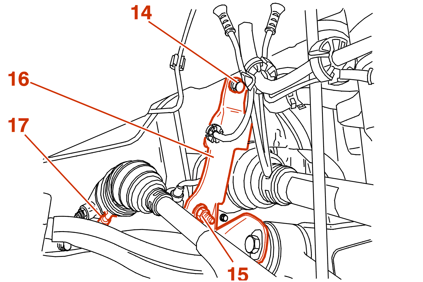
The bolt (14), To 5 da.Nm .
The bolt (15), To 5 da.Nm .
Bulkhead crossmember seal fastener (5), To 0,6 da.Nm .
The (7) fixing bolts of the steering column clamp to 2 danm .
The bolt (3) To 2,5 da.Nm .
The bolts (9) to 1.5 da.Nm .
The track rod ball joint nut to 3,5 da.Nm .
The wheels, To 9 da.Nm .