D4BP00A1 - 607
FITTING SPECIAL ALARM 607
1 - PRESENTATION

(1) Siren .
(2) Interior protection module .
(3) Interior protection sensors .
(4) Luggage compartment switch .
(5) Display LED .
(6) Interior protection disarming switch .
(7) High frequency remote control .
(8) Built-in systems interface (BSI) .
(9) Bonnet switch .
2 - COMPOSITION OF THE MODULAR ALARM : PART NO. 9671.X6

| reference | description | quantity |
|---|---|---|
| 1 | siren | 1 |
| 2 | interior protection module | 1 |
| 3 | interior protection sensors | 2 |
| 6 | interior protection disarming switch | 1 |
| 9 | bonnet switch | 1 |
| 10 | siren mounting plate | 1 |
| 11 | assembly instructions | 1 |
| 12 | clips | 2 |
WARNING : additional parts to be ordered, depending on the equipment level and the trim colour .

| reference | description | Part No. | quantity |
|---|---|---|---|
| 13 | roof console grid | beige FEX : 8146.H7 grey HZR : 8146.H8 |
1 |
| 14 | interior protection disarming switch mountings A : 1 switch B : 2 stalks |
beige FEX : 8214.PW grey HZR : 8214.PY beige FEX : 8214.PS grey HZR : 8214.PV |
1 |
3 - SCHEMATIC DIAGRAM
3 - 1 - ALARM - BASE LEVEL VEHICLE

| list of components | |
|---|---|
| 6202 | driver's door lock assembly |
| 6207 | front passenger door lock assembly |
| 6212 | rear left-hand door lock assembly |
| 6216 | luggage compartment switch |
| 6217 | rear right-hand door lock assembly |
| 6220 | door locking switch + alarm LED |
| 6222 | boot lock assembly |
| 8602 | interior protection unit |
| 8603 | switch |
| 8605 | siren |
| 8604 | interior protection sensors |
| 8611 | bonnet switch |
| BSI | built-in systems interface (BSI) |
3 - 2 - ALARM - LUXURY LEVEL VEHICLE

| list of components | |
|---|---|
| 6036 | window lift control board / rear-view mirror (driver's door) |
| 6037 | window lift control board / rear-view mirror (passenger door) |
| 6202 | driver's door lock assembly |
| 6207 | front passenger door lock assembly |
| 6212 | rear left-hand door lock assembly |
| 6216 | luggage compartment switch |
| 6217 | rear right-hand door lock assembly |
| 6220 | door locking switch + alarm LED |
| 6222 | boot lock assembly |
| 8602 | interior protection unit |
| 8603 | switch |
| 8605 | siren |
| 8604 | interior protection sensors |
| 8611 | bonnet switch |
| BSI | built-in systems interface (BSI) |
4 - FITTING
4 - 1 - VEHICLE PREPARATION
Open the bonnet .
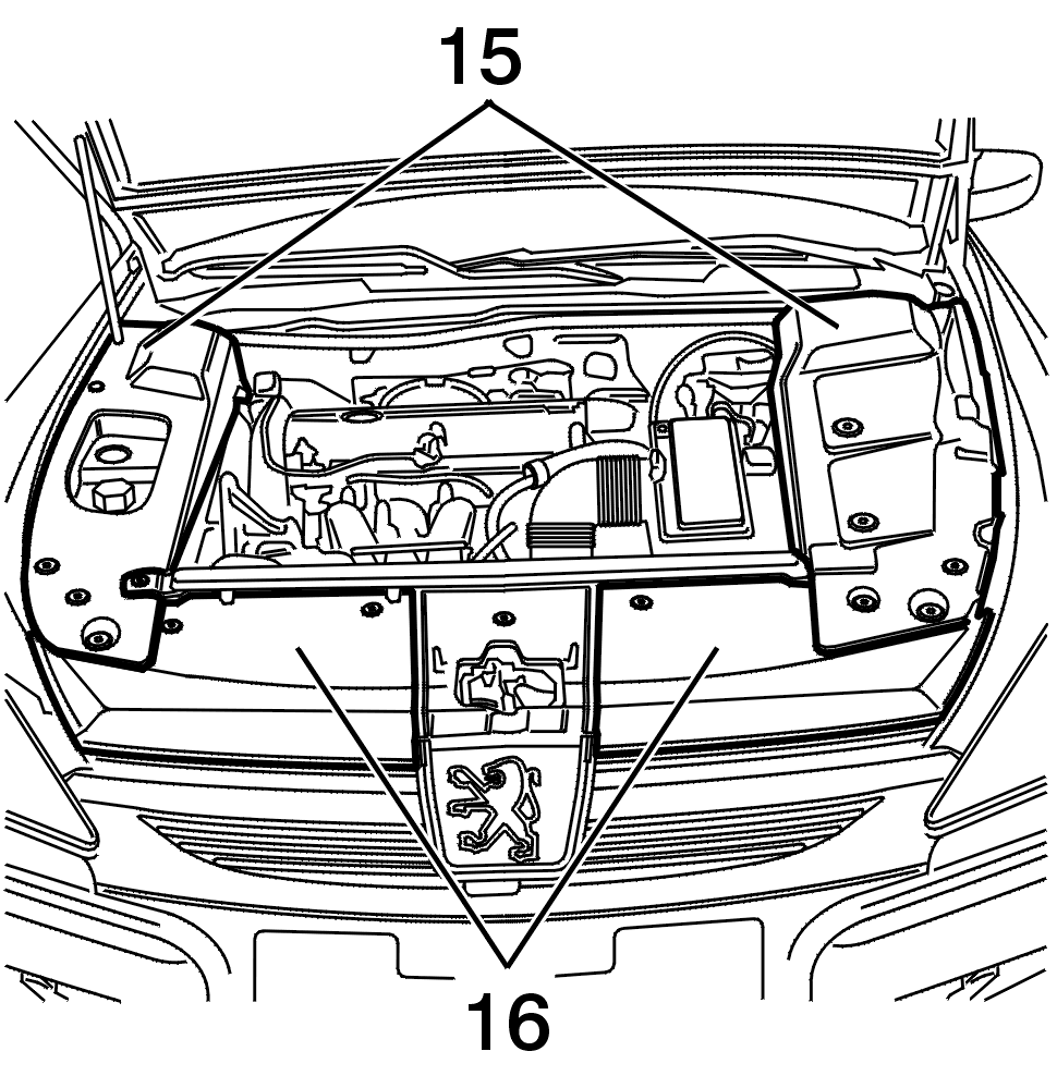
Remove :
Disconnect the battery + terminal .
Special feature : Dual battery .

Disconnect the battery (Ignition off) .
A battery must be disconnected :
IMPERATIVE : DISCONNECT THE STARTING BATTERY ; remove the auxiliary battery (17) supply fuse to cut off the electrical supply .
4 - 2 - FITTING OF THE SIREN (1)/BONNET SWITCH (9)

Route the bonnet switch (9) between the radiator and the engine compartment front panel support .
Connect the bonnet switch (18) connector (9) with the connector (19) provided on the engine compartment front panel support .

Route the bonnet switch wire along the power steering cooling pipe (20) .
Clip the bonnet switch (9) to the lock (21) .
Clip the bonnet switch wire onto the pipe using the clips (12) .

Remove the front spoiler(22) (On the right-hand side) .

Unclip the siren connector (23) provided on the front wheel arch, at the front .
Remove the wing inner panel mounting nut (24) .

Secure the siren mounting tab (10) on the wing inner panel mounting bolt (25) using the nut (24) .
Connect the connector (23) for the siren harness to the siren (1) .
Secure the siren (1) to the plate (10) .
4 - 3 - FITTING OF THE INTERIOR PROTECTION MODULE (2)/INTERIOR PROTECTION SENSORS (3)

Remove the right sun visor hook (26) .
Using a screwdriver blade unclip the console screen (27) .

Remove the roof console (28) mountings (29) .
Detach the roof console .
Disconnect the connectors .
Special feature : Radio telephone :
Remove the roof console .

Unclip the interior protection module black 6-way connector (30) provided on the upper roof crossmember .

Connect :

Clip the interior protection module (2) in the oblong hole (31) on the upper roof crossmember .

Pass the interior protection sensors (3) into the openings (32) .
Clip the interior protection sensors .

Re-connect the connectors .
Special feature : Radio telephone :
Fit :
4 - 4 - FITTING OF THE INTERIOR PROTECTION DISARMING SWITCH (6)

Unclip the storage compartment or the switch support (33) (According to specification) .
Disconnect the connectors .
Remove :

REPLACE THE GLOVE BOX OR THE SWITCH BRACKET ((33)) WITH SWITCH BRACKET ((14A)) OR ((14B)) (According to specification) .
Fit the interior protection disarming switch (6) supplied with the product on the support (14) .
Refit the controls .
Connect the connectors .
Clip the support (14) .
5 - INITIALISATION : TOOL DIAG 2000
IMPERATIVE : the vehicle must be configured after fitting to permit operation of the alarm .

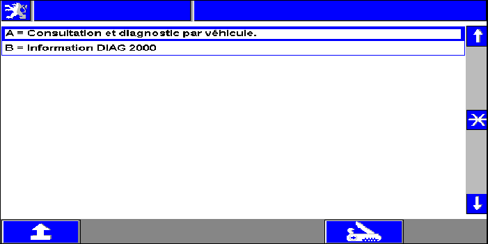
A = Consultation and diagnosis per vehicle .
B = Information DIAG 2000 .
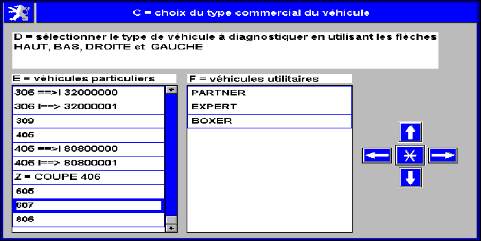
C = Choice of vehicle type .
D = Select the type of vehicle to be diagnosed using the up, down, right and left arrows .
E = Cars .
F = Vans .
Z = 406 coupe .

A = Consultation and diagnosis per vehicle .
G = Vehicle identification :

G = Vehicle identification .
H = Enter the number for accurate identification of the vehicle .

A = Consultation and diagnosis per vehicle .
I = Diagnosis .
J = Downloading .
K = Replacement parts .
L = Dealer fit .
M = Activation and disarming of the functions .

L = Dealer fit .
N = When fitting an accessory, it is necessary to reconfigure the vehicle .
O = This menu enables you to automatically configure all the ECUs necessary .
P = These accessories are :
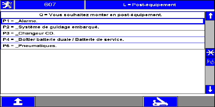
L = Dealer fit .
Q = You wish to fit as an accessory .
P1 = Alarm .
P2 = On-board navigation system .
P3 = CD player .
P4 = Dual battery unit / Battery .
P5 = Tyres .

P1 = Alarm .
R = Switch on the ignition .
S = Connect the portable to the test connector C001 .
P1 = Alarm .
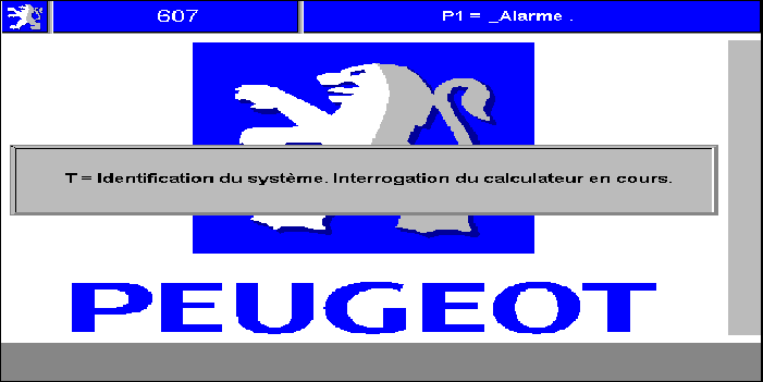
T = System identification - Reading of the ECU in progress .

P1 = Alarm .
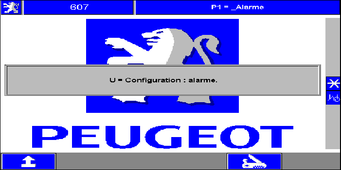
U = Configuration : Alarm .

P1 = Alarm .
V = Selection of destination :

U = Alarm configuration .
W = Configuration carried out .
X = Validate to continue .
P1 = Alarm .
U = Configuration : Alarm .
6 - REFITTING THE COMPONENTS
Proceed in the reverse order to removal .
Special feature : Dual battery :
After reconnecting the battery, reinitialise the ecus (audio equipment, displays/multifunction screen) and the one-touch electric windows .
Check the correct electrical operation of the equipment .
7 - HANDBOOK
See vehicle handbook .
NOTE : notice valid subject to product modification .