B1BG12K1 - 607 DW12TED4 ENGINE
REMOVAL - REFITTING POWER UNIT
1 - SPECIAL TOOLS
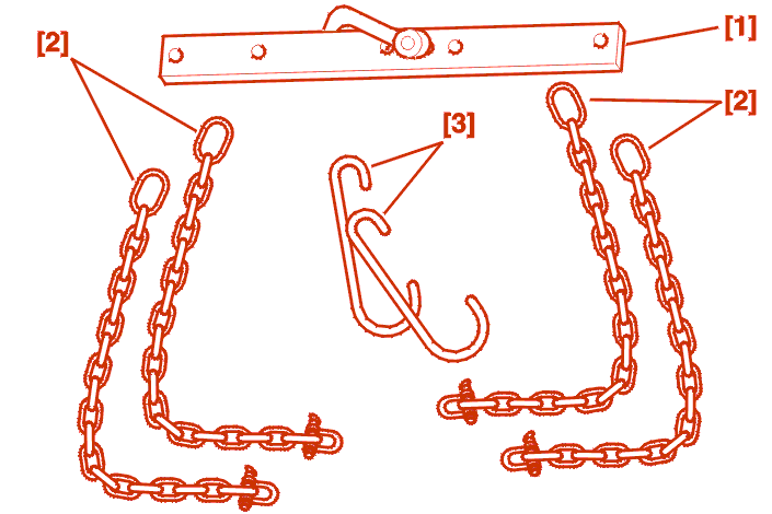
[1] cross beam (-).0102-D .
[2] Lifting chain (-).0102-M .
[3] lifting hooks (-).0102-J/(-).0102-G .

[4] Set of plugs (-).0188-T .
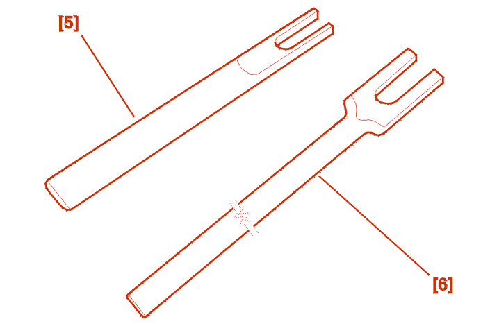
[5] Tool for unclipping the ball joints d.10 mm (-).0216-G1 .
[6] Tool for unclipping the ball joints d.13 mm (-).0216-G2 .
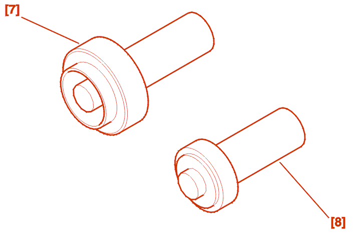
[7] fitting drift for final drive right-hand output oil seal (-).0332-B .
[8] fitting drift for final drive left-hand output oil seal (-).0332-A .
2 - REMOVAL
The power unit is removed from above .

Remove the style covers .
Disconnect the battery .
Remove the excess pressure ducts (1) - (2) .
Remove the air cleaner (3) and its outlet connection .
Raise the vehicle .
Remove :
Drain :
ML GEARBOX
Drain the gearbox .

ALL MODELS
Remove the air conduit (5) .
IMPERATIVE : remove the exhaust pipe to avoid damaging the flexible hose; this cannot withstand the torsion, traction or bending tensions caused by the removal of one of the power train supports .
Remove the torque reaction link (6) .
Remove the bolt (7) and the clip (8) from the air duct .
Block the hole of the turbo .
Disconnect the compressor electrical supply (9) .
Without disconnecting the hoses, move aside and clamp the air conditioning compressor (10) .
Unclamp the power steering circuit (11) (without opening the circuit) .

Remove the air cleaner bracket (12) and its sleeve .
Move aside the harness (13) .
Remove the protective shield (14) from the battery .
Uncouple the accelerator cable (15) .
Disconnect the accelerator potentiometer (16) connector .
Remove the screen (17) .
Remove the battery .

Remove the battery tray (18) .
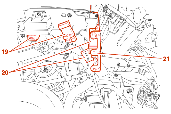
Unclamp and move aside the connectors (19) and the relays (20) .
Remove the separation panel (21) .

Disconnect the connectors (22) .
Disconnect the cables (23) .
Remove the support (24) .
Move aside the harnesses (25) .
Disconnect the earth cables (26) .
Disconnect and remove the control unit(s) with their brackets .
Disconnect and move aside the harnesses attached to the engine .
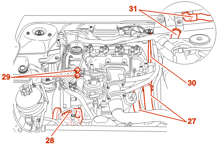
Move aside the hoses (27) .
Remove the radiator .
Protect the condenser with strong cardboard .
Without disconnecting the hoses, move aside and clamp the power steering pump (28) .
Unclamp and move aside the fuel supply ducts (29) .
Plug the holes using tool [4] .
Disconnect and move aside the power steering pipes (30) .
Move aside the heat exchanger ducts (31) .
HP AUTOMATIC GEARBOX
Uncouple and move aside the gearbox control .
ML GEARBOX
Uncouple and move aside the gearbox controls using tools [5] - [6] .

Disconnect the clutch control pipe (32) .
IMPERATIVE : protect the ends of the pipe and the clutch slave cylinder using the tools [4] .
ALL MODELS
Position the cross beam [1] fitted with its chains [2] and take the weight .
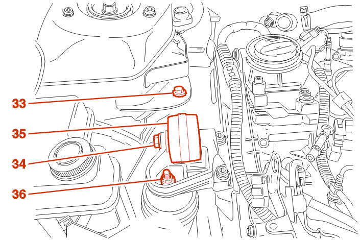
Remove :

Remove :
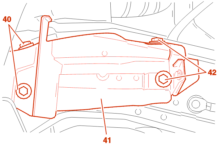
Remove :
Remove the power unit from above .
3 - REFITTING
Proceed in the reverse order to removal .
Always renew :
Use the drifts [7] - [8] to fit the final drive oil seals, having greased the space between the seal lips .
Fit :
Tighten :
Position the spacer on the gearbox shaft then coat it with PCAS SPAGRAM grease .
Position :
Lower the power train on to its mountings .
WARNING : centralise the power train before tightening the flexible mounting securing bolts .
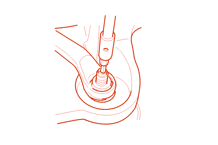
IMPERATIVE : apply a counter-torque to the flexible mount shaft when tightening the nut (36) .
Tighten :
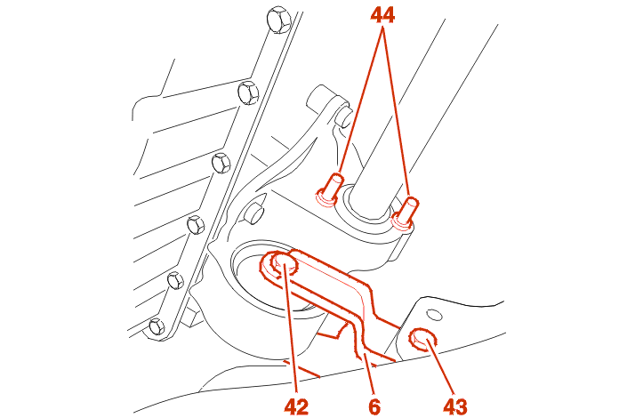
Refit the torque reaction link (6) .
Tighten :

Check the presence of the two spacers (45) .
WARNING : the anti-rotation nut (46) secures the compressor at its upper rear end .
REFIT THE COMPRESSOR IN THE ORDER OF ASSEMBLY SHOWN ABOVE .
Firstly tighten the bolts on the crankshaft pulley side to 4,2 da.Nm then the bolts on the oil filter side to 4,1 da.Nm .
Re-connect the connector (9) .
Tighten the drive shaft nuts to 34,5 m.daN .

Refit the pump respecting the order of assembly of the components .
Tighten (In order ) :
Continue the fitting operations in the reverse order to removal .
Reconnect the the clutch control pipe (32) .
BLEED THE CLUTCH HYDRAULIC CIRCUIT .
FIT THE ANCILLARY DRIVE BELT .
Continue the fitting operations in the reverse order to removal .
REFIT THE SOLENOID VALVES BRACKET .
Refill :
Tighten the wheel bolts to 9 da.Nm .
FILL AND BLEED THE COOLING SYSTEM .
Initialise the various ECUs .