B3EG0RK1 - 607
REMOVAL - REFITTING STEERING COLUMN
1 - REMOVAL
Push the driver's seat back as far as possible .
Switch off the ignition .
Remove the battery style cover .
Disconnect the battery negative cable ; Protect the cable and the negative terminal to prevent any contact .
Disconnect the negative cable from the battery in the boot (according to specification) Protect the cable and the negative terminal to prevent any contact .
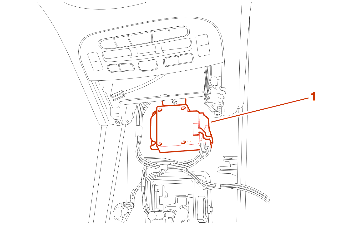
Disconnect the (1) 50-way connector (OR) .
Position the front wheels straight ahead .
Position the steerng column in the low outlet position and lock it .

Remove the bolts (1) .
Remove the trim (2) .

IMPERATIVE : push the knob (3) to immobilise it in relation to lateral movement of the steering column (knob travel (3) = 1 mm) .
Remove the bolt (4) .
Release the steering universal joint by moving aside the safety clip (5) .
Mark the position of the steering wheel in relation to the top suspension unit .
Lock the steering lock .
Unscrew a few threads of the steering wheel securing bolts .
Release the steering wheel from its splines by tapping the rim with your hands .
Remove the steering wheel securing bolts .

Mark the steering wheel and mark the column in order to ensure the correct position of the wheel in relation to the column on refitting .
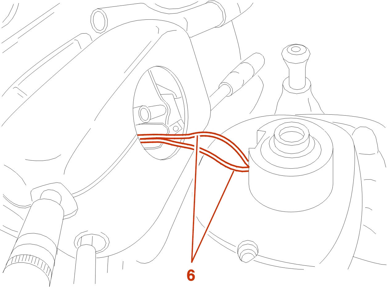
Remove the steering wheel carefully without pulling out the supply connector (6) .
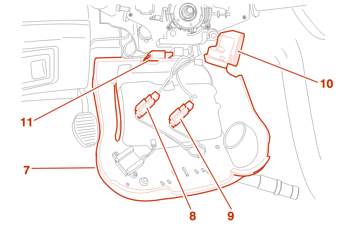
Move aside The steering column half shroud (7) .
Disconnect the connections (8), (9) .
Using a screwdriver, unclip and pull the analogue module (10), detach it from the steering wheel ignition lock and allow it to hang .
Unclamp and disconnect the connector (11) .
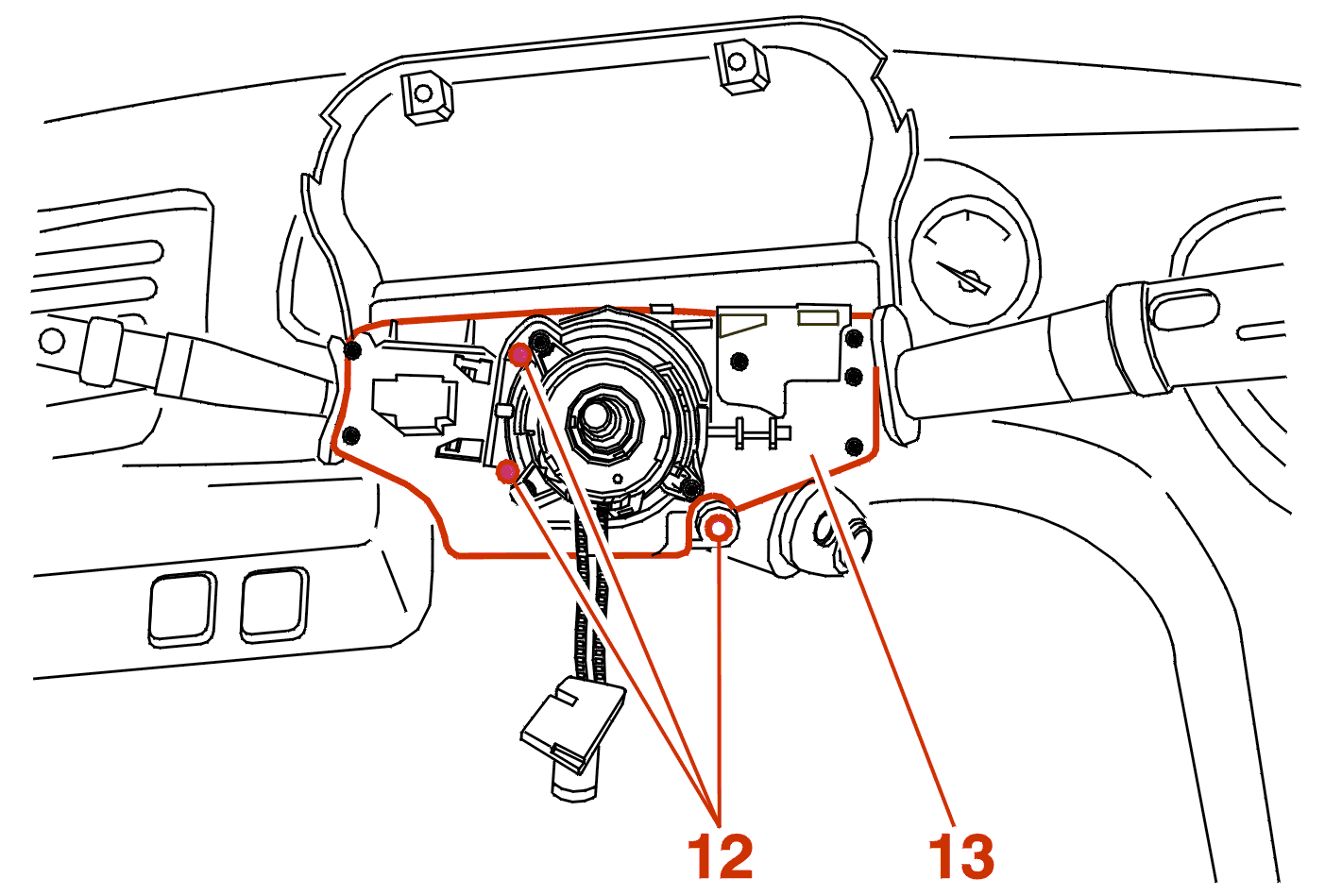
Remove the bolts (12) from the lights / wiper stalk bracket .
Move aside The stalk bracket (13) .

Disconnect the connectors (14) (15) .

Unclamp and disconnect the connector (16) .
DYNAMIC STABILITY CONTROL
Unclamp and disconnect the connector (17) .

Unclamp and disconnect the connector (18) .
ALL MODELS
Remove The stalk bracket (13) .

Remove the bolt (19) .
Move aside the bracket (20) .
Disconnect the connectors (21), (22), (23) .
DYNAMIC STABILITY CONTROL

Remove the drive ring (24) .
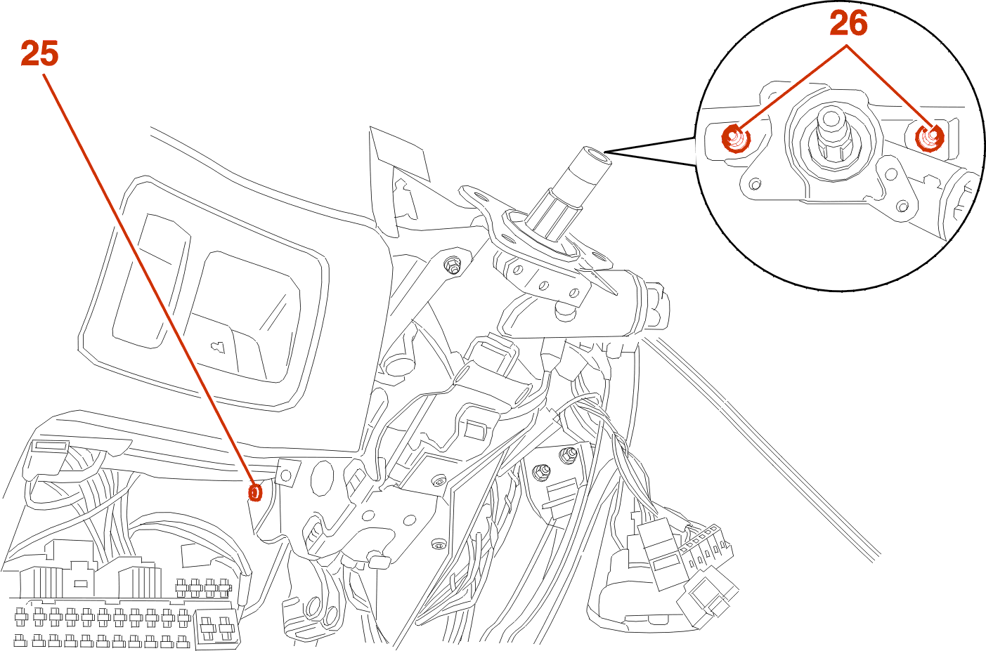
ALL MODELS
Remove the bolt (25) .
Remove the nuts (26) .
Grasp the steering column assembly and pull towards you in order to detach the rear part of the column bracket .
Remove the steering column assembly .

Remove the securing bolts (27) .
Move aside the accelerator pedal and its bracket .
Remove the bolts (28) .
Remove the seal (29) .

Remove the bolts (30) .
Remove the steering column shaft, including the lower universal joint (31) .
2 - REFITTING
Proceed in the reverse order to removal .
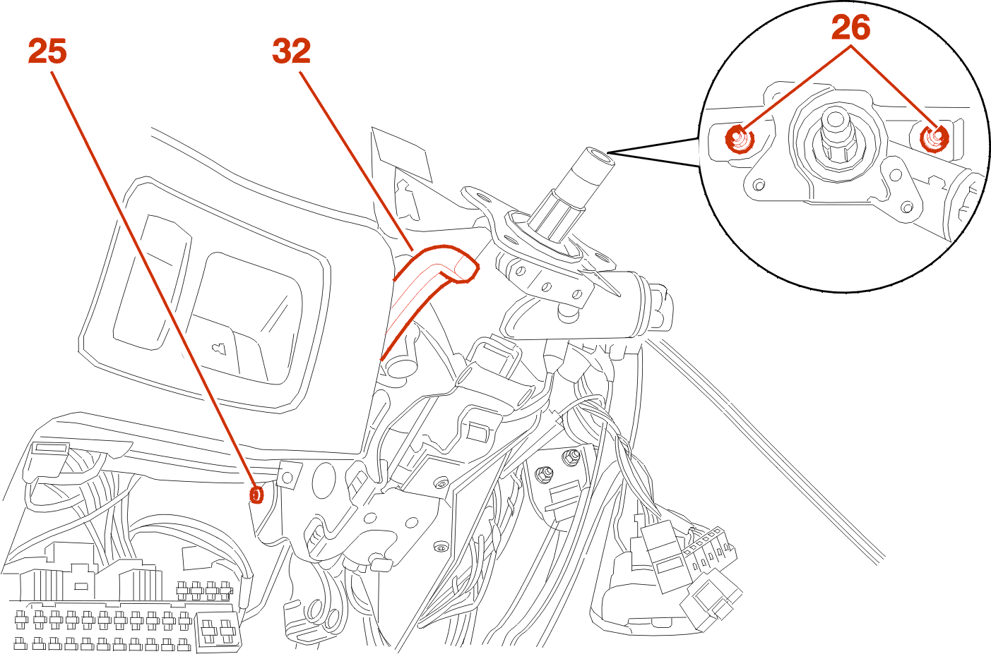
When refitting the steering column on its bracket, observe the following order of operations :

IMPERATIVE : when coupling the lower pin (31) and the steering column, do not rotate the lower pin (31) .
Refit the bolt (4) .
Tighten the bolt (4) to 2.5 da.Nm .
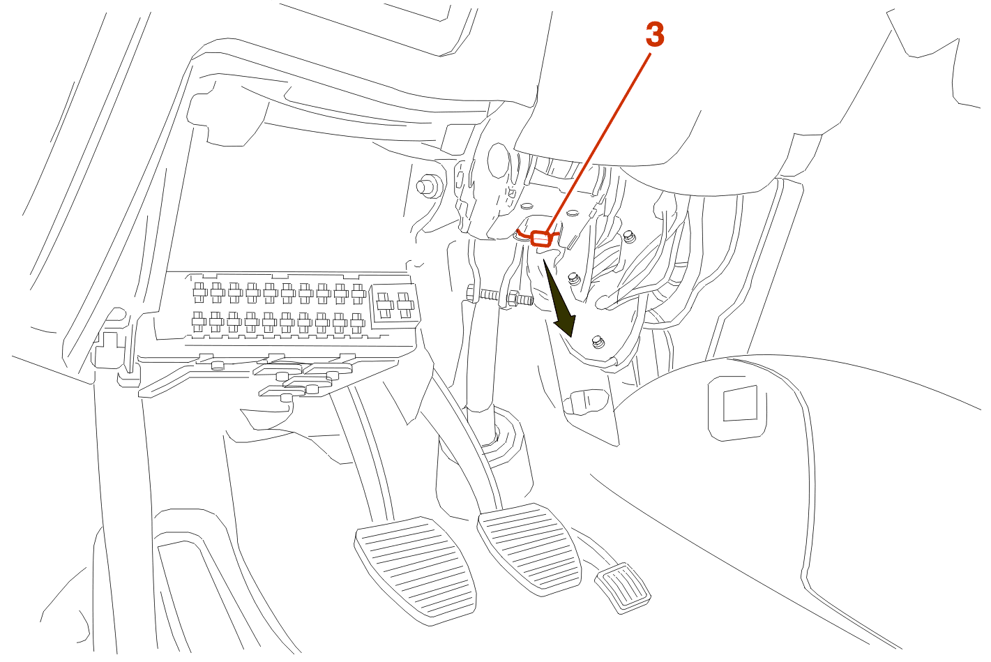
Pull the knob (3) .
Continue the fitting operations in the reverse order to removal .
DYNAMIC STABILITY CONTROL

When refitting the wiper / lights stalk bracket (13) place the drive ring (33) of the steering wheel sensor in place in the lugs (34) .
Replace the drive ring and wiper / lights stalk bracket assembly while at the same time engaging it in the grooves of the steering column .
ALL MODELS
Fit The stalk bracket (13) .
REFIT AND ADJUST THE ROTARY CONNECTOR .
Respect the marks made on dismantling .
Continue the fitting operations in the reverse order to removal .
2 - 1 - ACTIVATION : CENTRALISED SYSTEM FOR AIRBAG(S) AND SEATBELTS
IMPERATIVE : the surroundings of the air bags and the pre-tensioning seat belts must be clear of objects or occupants .
Switch off the ignition .
Connect the battery negative cable .
Driver's side, door open, switch on ignition, while keeping clear of the deployment zone of the steering wheel module .
Check the correct operation of the system by means of the graphic on the instrument panel .
3 - REFITTING (CONTINUED)
Check that the electrical accessories operate correctly .
Carry out the initialisation procedure for the injection ignition control unit, Using the TEP/DIAG 2000 diagnostic equipment .
DYNAMIC STABILITY CONTROL
Programme the steering wheel angle sensor using the diagnostic equipment DIAG 2000 .
ALL MODELS
Tightening torques :