C5CG14K1 - 607
REMOVAL - REFITTING REAR SCREEN
1 - TOOLING

[1] FEIN electric knife assembly .
Contents of kit :
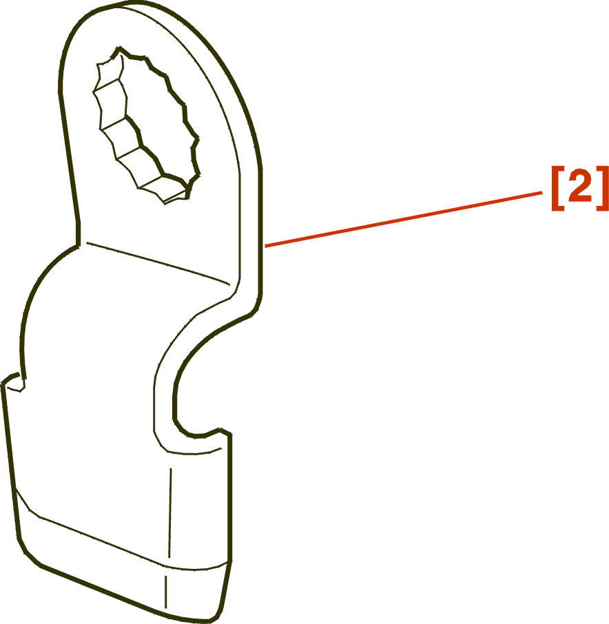
[2] Shovel blade N° 146 .

[3] Jointed suction caps .
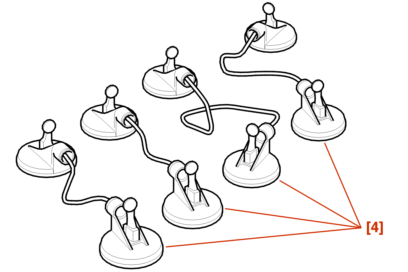
[4] Suction caps with wires .
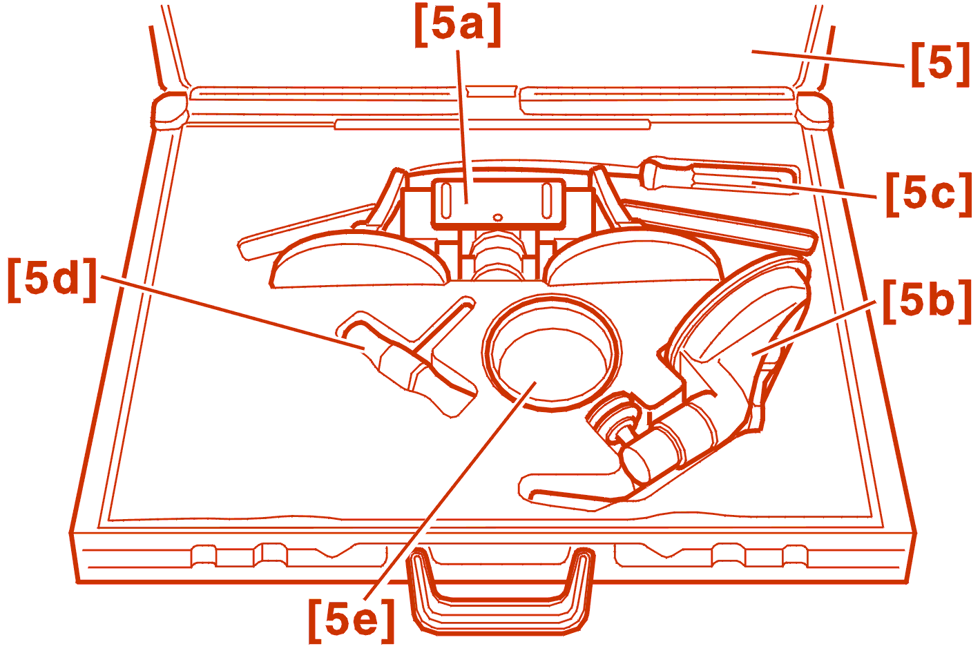
[5] Set of glass components :
2 - BONDING KIT
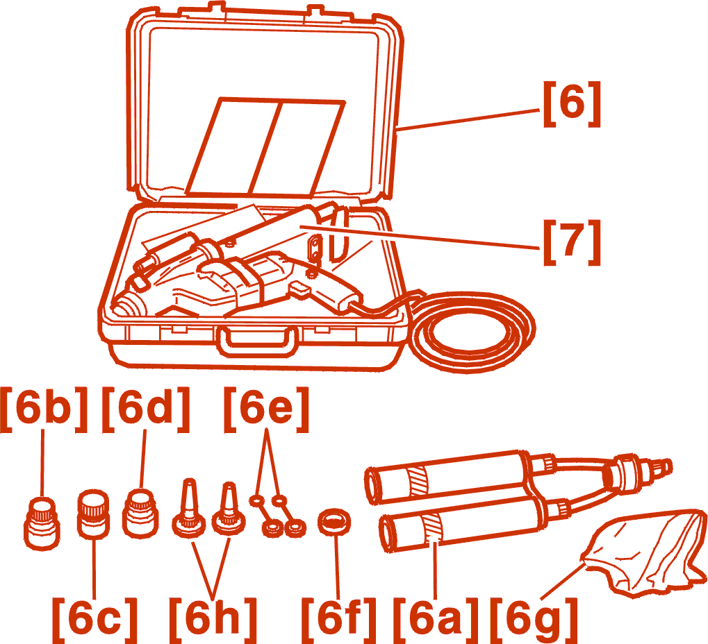
[6] Adhesive kit (quick set) :
[7] gun .
Use (X) :
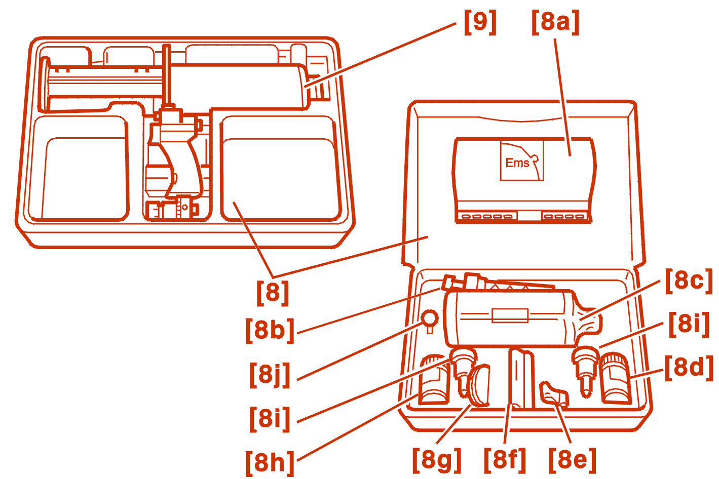
[8] Adhesive kit (quick set) :
[9] gun .
NOTE : the following single component adhesives can be used .

[10] Compressed air gun .
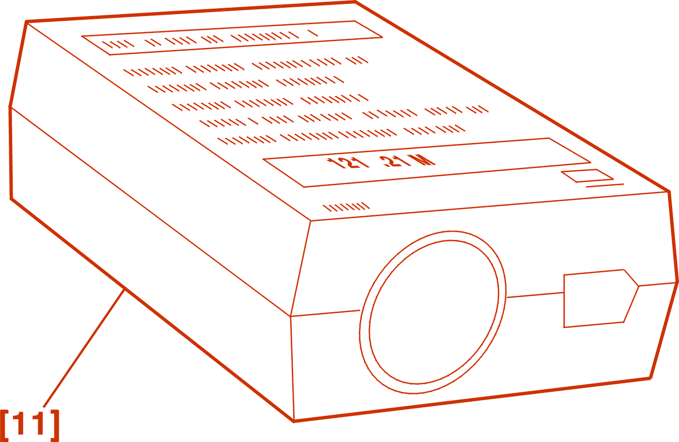
[11] Cartridge heater (To pre-heat the ultra-rapid cartridges) .

[12] Bonding kit :
3 - REMOVAL
Remove :
Disconnect the rear screen electrical connections .
Fold the connection terminals back against the glass and towards the centre of the vehicle .
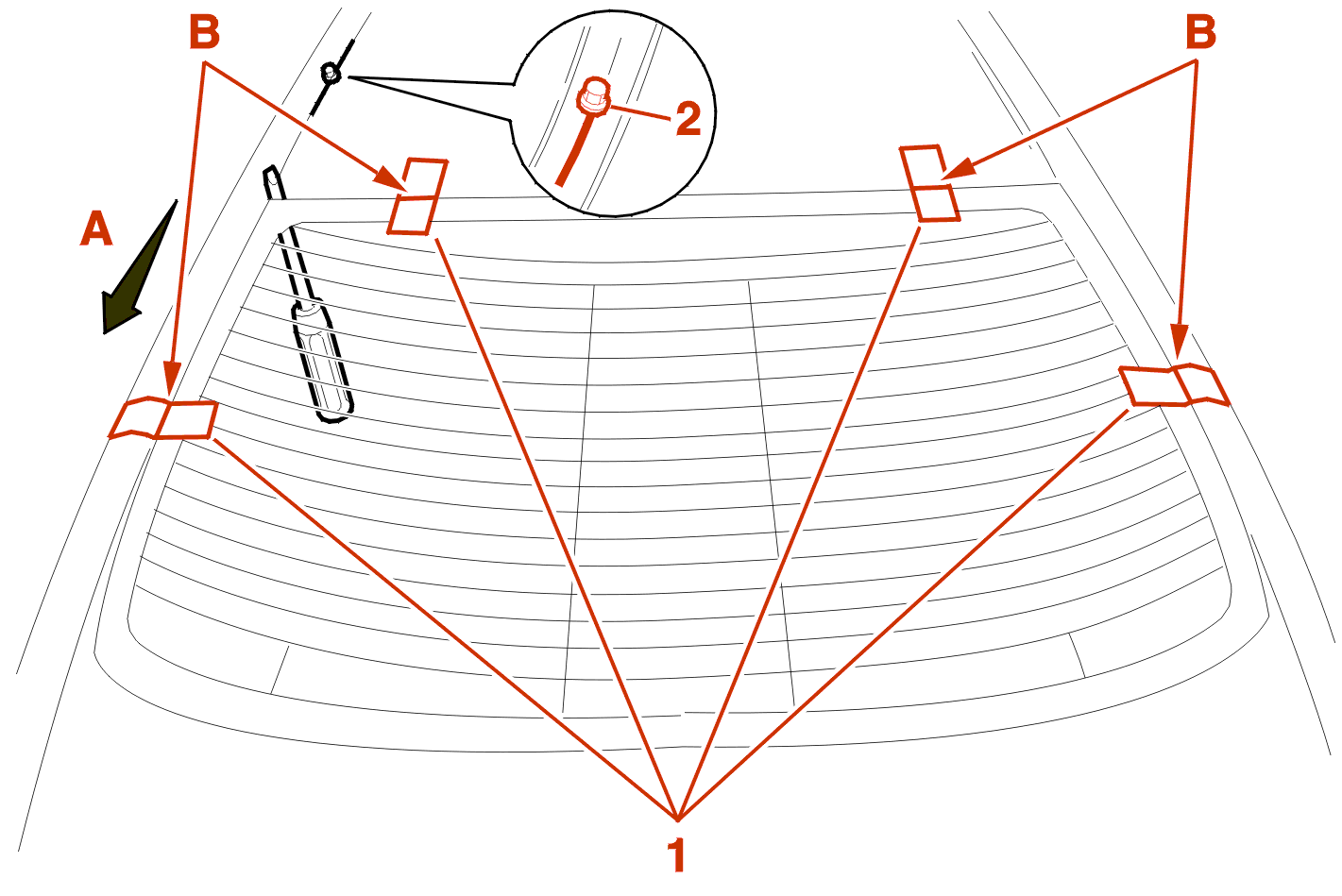
NOTE : in the event that the rear screen is retrieved, place adhesive strips (1) as shown above, and cut them in B .
Attach the cutting-out wire to the mounting 2 (maximum length of bolt 10 mm, at the roof bar mounting points) .
Pass the wire under the rear screen following A, all around the edge .
Pass the awl through the bead of adhesive, in the top left corner of the rear screen .
Thread the cutting wire into the awl and pass it towards the interior (approximately 50 cm) .

Secure the end of the cutting wire (3) in the winding device .
WARNING : when tensioning the cutting wire, ensure that the wire is placed under the rear screen correctly .
Cut the first section to the centre of the rear screen .
WARNING : at the slightest resistance of the wire on cutting, slacken it and help it to pass the obstacle (support shims, excessively thick bead of adhesive or panel junction) .
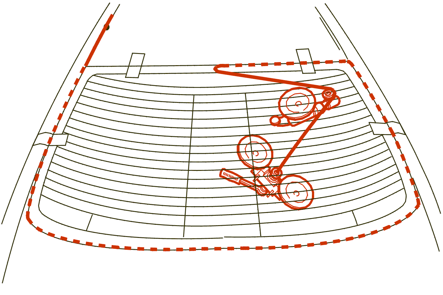
Move the winding device as indicated on the diagram and install the guide pulley in the upper rounded section of the glass .
Route the cutting wire as indicated on the diagram .
Cut out the glass until the cutting wire is no longer guided by the guide pulley .
Then, remove the guide pulley and continue the cut .
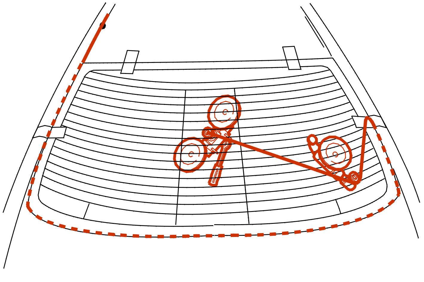
Cut out in accordance with the above view, in the same conditions as previously .

Cut out in accordance with the above view, in the same conditions as previously .
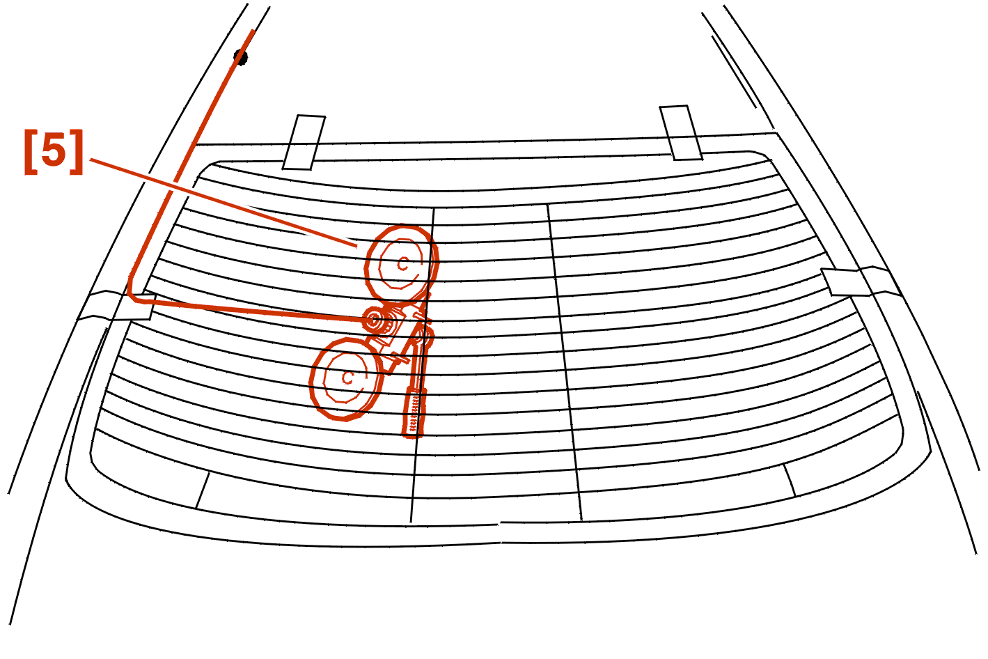
Move the winding device [5] as indicated on the diagram and finish the cut .
Remove the rear screen using double suction cups [3] .
4 - REFITTING

For all the following operations, keep the boot lid open as shown in fig. .
4 - 1 - PREPARATION OF THE FLANGE AND OF THE REAR SCREEN
Protect the rear shelf frame and the seats .
Fit blade [2] no.146 to the electric knife .
Deburr the beads of adhesive on the rear screen and the flange .
Replace the 2 lower shims which serve as stops for the rear screen .
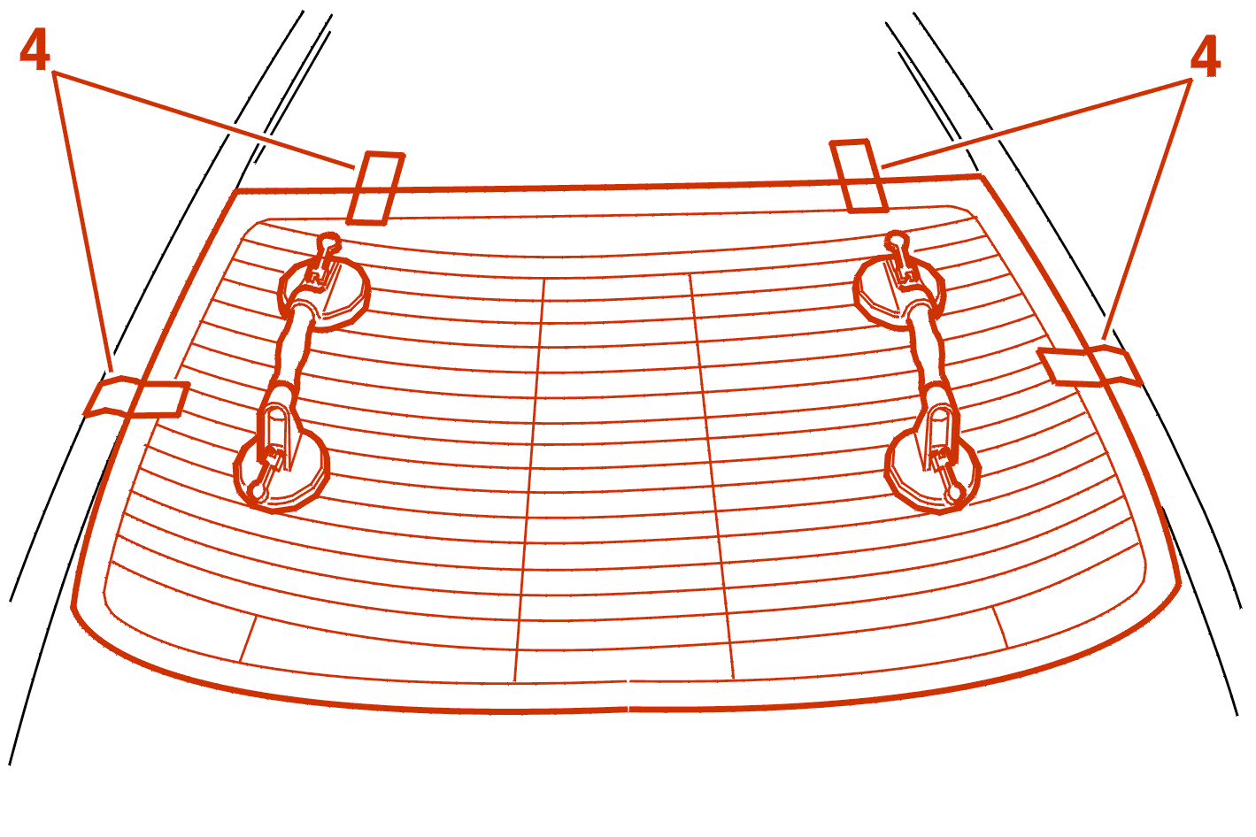
Offer up the rear screen onto the aperture .
NOTE : if the rear screen is replaced, centralise the screen and position adhesive strips (4) as shown above, then cut the strips .
Remove the rear screen .
Touch up with anti-corrosion product .
Degrease the flange and the rear screen using a product chosen from the bonding kit .
Allow to dry for 10 mn .
Apply the metal and glass primers selected from the adhesive kit .
Allow to dry for 10 mn .
4 - 2 - BONDING
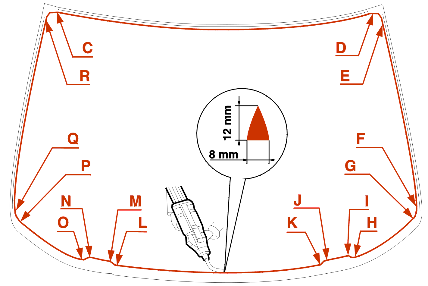
Fit the mastic mixer assembly to the extruder gun .
Take the nozzle supplied in the bonding kit .
Cut the nozzle to 8 mm dia. at 12 mm from the tip .
Apply the bead of adhesive :
IMPERATIVE : no more than 8 minutes must elapse between applying the mastic and positioning the glass (for the quick bonding adhesive mastics) .
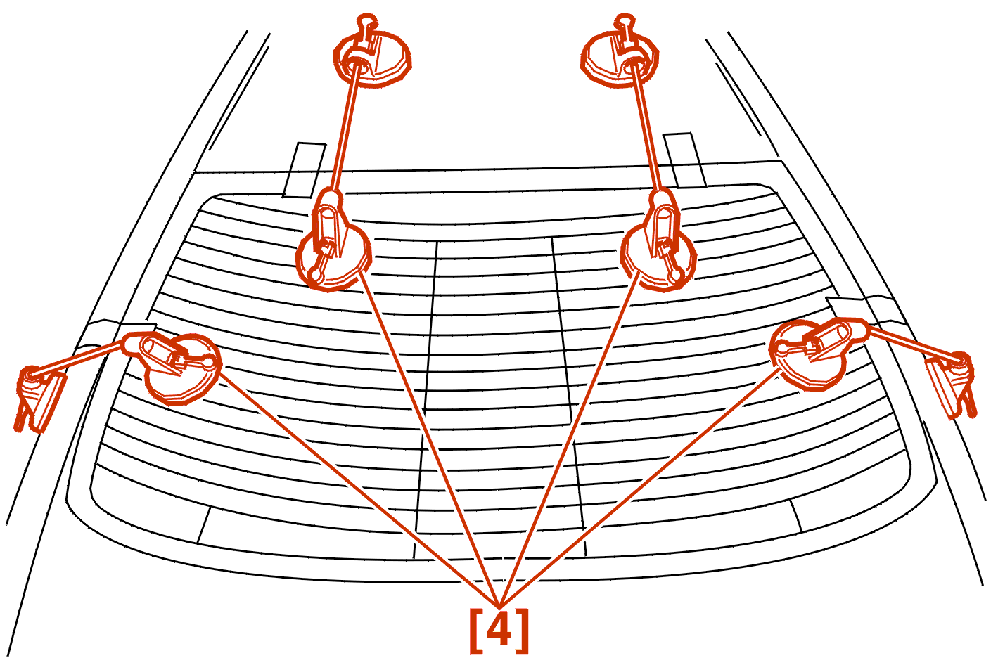
Position the rear screen in relation to the adhesive tape .
Exert a constant pressure using the suction cups with wires [4] .
Allow to cure for 30 minutes before handling .
Connect : The electrical connections .
Check :
Proceed in the reverse order to removal .